This thread has been locked.

If you have a related question, please click the "Ask a related question" button in the top right corner. The newly created question will be automatically linked to this question.

FDC1004: Shielding of Capacitive liquid level sensing

Part Number: FDC1004

Hello TI,

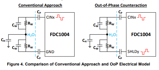
I have been working with the fdc1004 for a while now. I'm trying to use the liquid level sensing technique from your app-note: http://www.ti.com/lit/an/snoa925/snoa925.pdf and http://www.ti.com/lit/an/snoa958/snoa958.pdf

I have managed to get it to work so far by using your EVM GUI and I have also managed to make it work with my arduino. 
My problem is that even though it works, I can't seem to figure out the shielding on the arduino. It works without problems on the EVM module through the GUI.

My setup is like this:

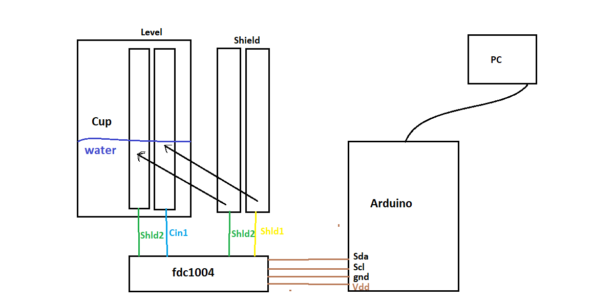
I use the library from Beshaya: https://github.com/beshaya/FDC1004

I can make the readings, but the shield doesn't seem to work properly. I was wondering how the shield works and why I need to connect the ground electrode to shield instead of ground as stated in the application note. Is it just a excitation signal opposite of the excitation doing the capacitive reading or do I need to add more to it. Could anyone explain how this shield works or how to apply it through my software?

Thanks in advance! :) 

  • Hi Morten,

    In general, the FDC1004's shield is identical to the excitation signal on CINx. With no voltage difference between the two signals there will not be any capacitance between them. When the shield covers the CINx sensor or trace, any stray capacitances (like a human touching the board) will be between the shield and ground instead of CINx and ground. You can read more about the shield in section 8.3.1 of the FDC1004 datasheet. You do not need to control the SHLDx pins manually; they will automatically behave as described in section 8.3.1 depending on how you configure your CINx measurements.

    The Out-of-Phase liquid level sensing technique works by holding the liquid at a fixed potential and using a differential measurement. CINx and SHLDy are 180 degrees out of phase when the FDC1004 is configured for differential measurement. This keeps node C_H at a fixed potential. In the conventional approach, the parasitic capacitance C_H would be in parallel with the liquid level capacitance measurement between CINx and ground, and would therefore add to the measured capacitance and interfere with the liquid level measurement. In the Out-of-Phase technique, C_H will be eliminated by the differential measurement between CINx and SHLDy, because both pins will see it as a constant capacitance to ground. 

    Best Regards,