This thread has been locked.

If you have a related question, please click the "Ask a related question" button in the top right corner. The newly created question will be automatically linked to this question.

FDC2214EVM: Proximity Sensing Range

Part Number: FDC2214EVM
Other Parts Discussed in Thread: FDC2214,

Dear TI

I used a webench designer tool to calculate the sensor diameter and its proximity sensing range. The results in the figure below.

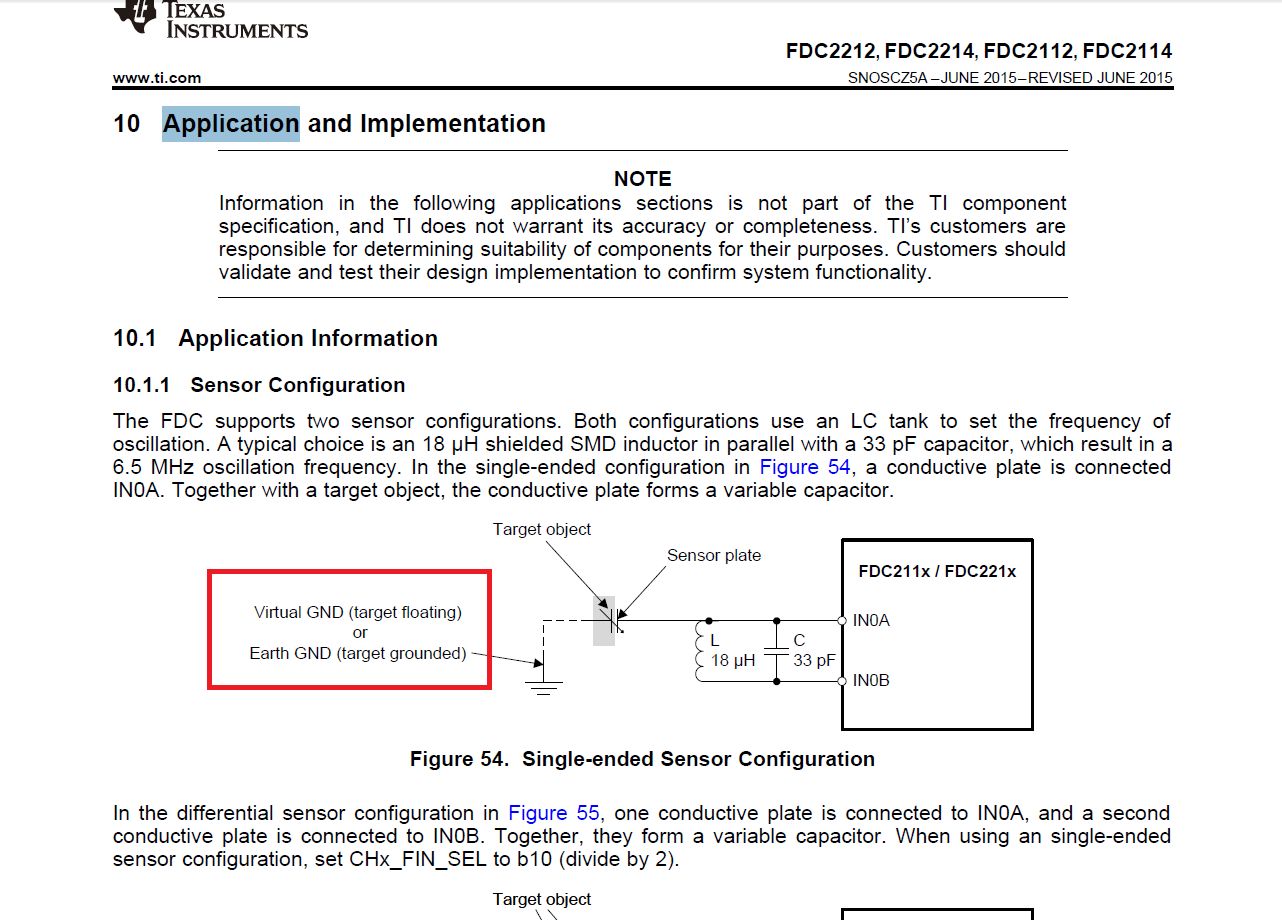
I am using a FDC2214 EVM with our own SENSOR PLATE which has a diameter of 2 cm connected to INA and  GROUND PLATE with a diameter of 2 cm connected to INB of Channel 3.

Distance between sensor and ground plate is 0.16 cm (PCB thickness),  but the proximity sensing range didn't reach to 12 cm. Its only 3 cm.

Here are my questions:

1. How to get this kind of proximity sensing range by using the same sensor diameter?

2. What parameters or components have to change?

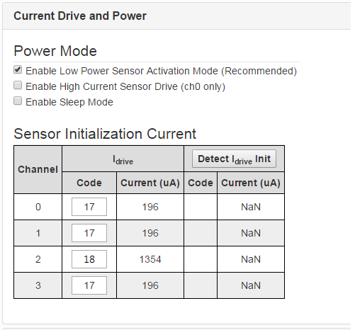
3. Does the configuration of sensor is correct ?

Waiting for your response. Thank you!

Best Regards,

Janine Lin

  • Hi Janine,

    In general, capacitive sensors are more sensitive to proximity sensing when there is no grounded plate nearby. Unless it is a required part of your system, I would not recommend using it.

    The sensing range is also affected by RCOUNT. A larger RCOUNT translates to a more sensitive sensor and a slower sample rate.

    Also ensure that the sensor oscillation amplitudes of both INxA/INxB are between 1.2-1.8V, which is where the sensor will be the most sensitive. For help with this, please see this application note: www.ti.com/.../snoa950.pdf

    If you have not seen it already, you may find this application note about proximity sensing using the FDC2x1y devices helpful: www.ti.com/.../snoa940a.pdf

    Best Regards,
  • Dear Kristine


    Thank you for the quick response.

    Here are my follow up questions.


    1. What is the maximum RCOUNT?

    2. If there is no grounded plate, only sensor plate connect to INxA. How about the INxB?

    3. After setting the Idrive code, do I need to press the "Detect Idrive Init"? 

    4. In the datasheet it says, for single channel set CHx_FIN_SEL to "divide by 2", set CHx_settle count to > 3 and set CHx_Rcount to >8.  In configuration setting, which parameters have to set? 


    5. I used a sensor plate without ground plate with a diameter of 2 cm, but still the sensing range is only 2.5 cm. 

       What are the rules to reach 12 cm by using the same sensor diameter?

    Thank you

  • Hi Janine,

    1. The maximum RCOUNT is 0xFFFF, found in section 7.6.10 of the datasheet.

    2. When the sensor is only connected to INxA, this is a single-ended configuration. Though doable, the downside of this configuration is that the sensor oscillation amplitude can become unbalanced, meaning the amplitude could be outside of the recommended range for half of the oscillation period. Instead, we recommend a differential configuration, in which an identical sensor is connected to INxB. Section 10.1.1 of the datasheet has more information about both configurations.

    3. No, do not press "Detect Idrive Init." This will override your current Idrive settings with the LDC's best guess for an appropriate Idrive setting. Once you update the Idrive registers the changes in the drive current will immediately take effect.

    4.These settings are not available in the configuration tab of the GUI. You will need to go to the register tab of the GUI to control these settings. Please see the register map in the datasheet for details on how to set these registers.

    5. You may not be able to reach a 12cm sensing distance with a 2cm sensor. The sensing range depends upon many variables, including the sample rate, the size of the target, the potential of the target, and how electrically noisy the sensing environment is. In general, a large, grounded target will provide the strongest response, which can increase detection distance. A slower sample rate and lower noise floor allow for smaller target interactions to be reliably detected, which can also increase detection distance. A larger sensor plate will also increase detection distance.

  • Dear Kristin

    Thanks for the response.

    1. What is the difference between virtual ground and earth ground?

    2. Does the target should be connected to  ground? How about if our target is plastic?

    3. This is the result from the designer tool, where the sensor dimension is 2 cm and the detection target is human hand.

        What is the solution to reach this kind of sensing range ?

    4. How to set if i use internal clock oscillator in GUI? In the datasheet it says, for single channel use  35Mhz. While for multiple channel its 55 Mhz. 

       But in the GUI, i am not able to edit the value for internal oscillator. 

  • Dear Kristine

    Any update?

  • Hi Janine,

    1. I interpret virtual ground as AC ground, so either a power plane or a ground plane. Earth ground has a potential of 0V and is connected to earth. Why do you ask this question?

    2. The target does not have to be connected to ground, but a grounded target will have a stronger response. You do not need to ground a plastic target.

    3. The Webench Tool is available to give general guidelines about the type of sensing range that could be achieved for given sensor parameters. This sensing range may not be achievable in all environments. As I previously mentioned, the sensing range depends on many variables. You will need to experiment with different sensor sizes and sample rates to achieve a reliable 12cm sensing range.

    4. The internal oscillator is not configurable. Its frequency varies between FDC devices, with a minimum of 35MHz and a maximum of 55MHz. You can only decide between using either the internal oscillator or an external reference clock.

    Best Regards,
  • Thank you Kristin.

    1. I have seen the virtual GND and earth GND in the application information of the data sheet.

    2. What is sample rate and how to do it in GUI?

    3. This graph is from datasheet , page 45. How to reduce the sample rate in GUI ?


    4. Does the capacitor value in the graph is the "C" of "LC tank"?

    5. Please guide me how to set this in Register. Please refer to the red box. Thank you.

  • Hi Janine,

    1. Thank you for your explanation. My previous explanation of virtual and earth ground is consistent with this use.

    2. The sample rate is how quickly the FDC device can make frequency measurements and store them in the DATAx registers. You can change the sample rate by changing the RCOUNT_CHx and SETTLECOUNT_CHx registers. Page 16 and 17 of the datasheet contain more information about how to calculate your sample rate using your RCOUNT, SETTLECOUNT, and FREF values. In the GUI, use the Register Page to change the RCOUNT and SETTLECOUNT registers. Section 2.6 of the FDC2214EVM describes how to do this. The GUI will also calculate the sampling time on the Configuration page.

    3. I answered this question above.

    4. The capacitance value measured by the FDC2x1y devices will always include both the capacitor in the LC tank and any other capacitances affecting the LC tank. This includes capacitance between the sensor and the target, capacitances between the sensor and the environment, and parasitic capacitances on the INxA/INxB traces.

    5. You can set this register using the same method I described in answer 2 above. More details about individual registers can be found in the Register Maps section of the datasheet (9.6).

    Best Regards,
  • Thank you Kristin.