This thread has been locked.

If you have a related question, please click the "Ask a related question" button in the top right corner. The newly created question will be automatically linked to this question.

AWR1642: ADC Data Units

Part Number: AWR1642

Hi,

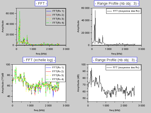
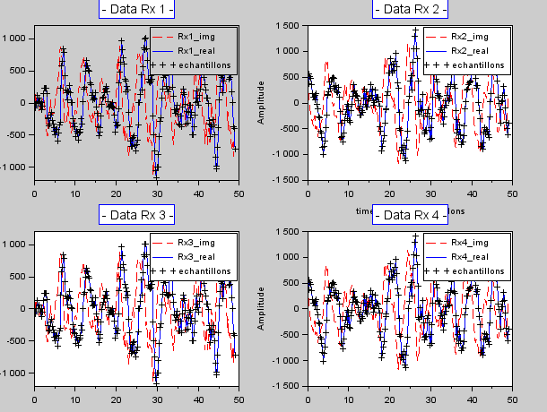
After I read the ADC data, I plot theses datas and the FFT and I obtained this :
But I have few questions :

1) What is the unit of the Y axis of ADC data ? mVolt ? Volt ? Or another ?

2) Is it normal that the 4 Rx antennas do not acquire the signal received at the same time? We see that the signal is different on each Rx.

3) And for the FFT graph, what is the unit of the Y axis? Because when I put the Y axis in log (dB), I have the same values ​​as the visualizer, so I deduce that the values ​​are good, it's just the unit that I can not find.

4) For the ADCdata plot and the FFT plot, what are the max and the min value that can be measurable by the kit ?

Thanks,

Kévin.

  • Hi,

    You can compare your graphs with the graphs in the mmwave studio documentation.

    Thank you
    Cesar
  • Hi,
    I'm sorry but I only found theses infos :
    - unit "code" for the ADCdata, and it's not a true unit,
    - unit "relative power" for the FFT, and it's not clearly explained (no formula).
    And for the other questions, there's no informations in the datasheet.

    Thanks,
    Kévin.
  • Kevin,

    For your first question, the unit for the ADC data is the ADC code. The resulting values are determined by the precision of the ADC. This can be specified as either 12-bit, 14-bit, or 16-bit. Based on this, since you are using complex mode, you values can span from [-(2^n),2^n-1]. This is a unit since all the ADC spits out is a code. It has no unit so this question was properly addressed in the initial response.

    For your second question, this depends on a variety of factors. If the sensor is placed in a bore sight configuration to the target object, then in theory the received signal would arrive at all 4 RX antennas at the same time. The slight differences in arrival time at each RX antenna allow us to determine the angle at which a detected object is located relative to the sensor. In most scenarios, the reflected signal from the TX antenna will not arrive at the four RX antennas at the same time.

    For your third question, the unit for the FFT graphs is dB. The max power output on the AWR1642 is 12 dBm. The visualizer uses dB as the units instead of dBm.

    For your fourth question, the min and max values for the ADC data codes are [-(2^n),2^n-1] where n is the number of ADC bits. There are no min and max values on the FFT plots.

    Regards,
    Kyle