A related question is a question created from another question. When the related question is created, it will be automatically linked to the original question.
If you have a related question, please click the "Ask a related question" button in the top right corner. The newly created question will be automatically linked to this question.
DRV411: About the differential amplifier, there is no input bias current and input offset current.
Part Number: DRV411 Other Parts Discussed in Thread: DRV421
Dear TI,
could you please provide me the input bias current and input offset current informations of the differential amplifier used to measure the current on compensation coil?
Thank you for using the forum to get your questions answered.
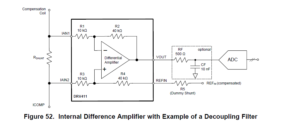
Please think of the impedance as seen in Figure 52 in the data sheet. With a differential impedance of about 20kΩ and common mode of 25kΩ when Vout = Vref. This of course will change depending on your Input, RefIN and Vout. We would assume that Rshunt << 20k
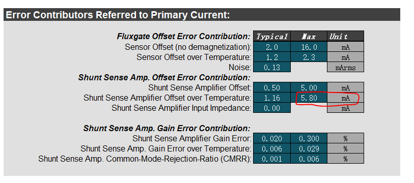
Could you please have a look at the attached picture which I capture from DRV421 tool,looks the maximum offset current is 5.8mA? May I know how do you define this value? And this value looks very big?
This offset will depending on the number of winding and your shunt resistor. This error is calculated for the primary current not the current through the compensation coil.
Your system gain can be seen on Calculated System Parameters. This does include the Gain of the Difference amplifier. So from you numbers I assume that the Gain is 0.020 V/A. That means the output voltage is 0.02V for every A in the primary. So the error in the primary due to the Output offset off the Diff amplifier is just 100µV / 0.020V/A giving an error of 5.00mA for room. The calculator uses 100µV instead of the specified 75µV.
Over temperature you need to include the drift which is 2µV/C. From the numbers provided I assume you have your max temperature at 85C. This give a delta of 60C. 60C * 2µV = 120µV.
The error you see is not the worst case as it uses the 120µV in the calculator vs 75µV + 120µV = 195µV. This offset leads a 9.75mA error worst case at 85C. I will need to have that corrected. For the correct drift and the lower output offset voltage. For temporary solution add about 39.5° to the Max Operating Temperature.