Other Parts Discussed in Thread: PGA460, LM1117, LM317, TPS5410
Hi!
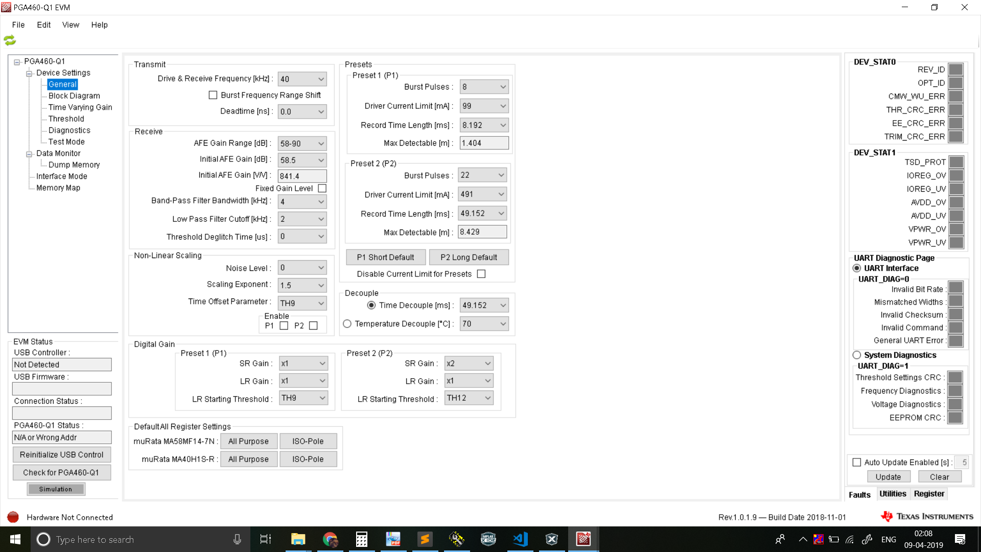
Our setup is as following:
A 12 Volt Car Battery going directly to PGA460 and Epcos TDK Transformer. Transducer is a 40KHZ Osenon Closed Top rated for 160Vpp. Our hardware is made up of 2 PCBs, the base board contains a microcontroller and associated power supply and 2nd PCB contains the PGA, Transformer and Transducer. The two boards are connected using a cable of length 10 cm on TTL UART interface at 3.3 Volts.
Attached is our EEPROM settings files.
;GRID_USER_MEMSPACE
00 (USER_DATA1),00
01 (USER_DATA2),00
02 (USER_DATA3),00
03 (USER_DATA4),00
04 (USER_DATA5),00
05 (USER_DATA6),00
06 (USER_DATA7),00
07 (USER_DATA8),00
08 (USER_DATA9),00
09 (USER_DATA10),00
0A (USER_DATA11),00
0B (USER_DATA12),00
0C (USER_DATA13),00
0D (USER_DATA14),00
0E (USER_DATA15),00
0F (USER_DATA16),00
10 (USER_DATA17),00
11 (USER_DATA18),00
12 (USER_DATA19),00
13 (USER_DATA20),00
14 (TVGAIN0),8D
15 (TVGAIN1),EE
16 (TVGAIN2),EF
17 (TVGAIN3),11
18 (TVGAIN4),48
19 (TVGAIN5),28
1A (TVGAIN6),C0
1B (INIT_GAIN),C0
1C (FREQUENCY),32
1D (DEADTIME),00
1E (PULSE_P1),68
1F (PULSE_P2),16
20 (CURR_LIM_P1),47
21 (CURR_LIM_P2),D6
22 (REC_LENGTH),BB
23 (FREQ_DIAG),00
24 (SAT_FDIAG_TH),22
25 (FVOLT_DEC),69
26 (DECPL_TEMP),0F
27 (DSP_SCALE),00
28 (TEMP_TRIM),00
29 (P1_GAIN_CTRL),C1
2A (P2_GAIN_CTRL),09
2B (EE_CRC),0C
40 (EE_CNTRL),00
41 (BPF_A2_MSB),87
42 (BPF_A2_LSB),07
43 (BPF_A3_MSB),F3
44 (BPF_A3_LSB),72
45 (BPF_B1_MSB),06
46 (BPF_B1_LSB),47
47 (LPF_A2_MSB),7C
48 (LPF_A2_LSB),D3
49 (LPF_B1_MSB),01
4A (LPF_B1_LSB),97
4B (TEST_MUX),00
4C (DEV_STAT0),80
4D (DEV_STAT1),00
5F (P1_THR_0),AC
60 (P1_THR_1),CC
61 (P1_THR_2),CC
62 (P1_THR_3),AC
63 (P1_THR_4),CC
64 (P1_THR_5),CC
65 (P1_THR_6),FB
66 (P1_THR_7),5A
67 (P1_THR_8),D3
68 (P1_THR_9),18
69 (P1_THR_10),C6
6A (P1_THR_11),3A
6B (P1_THR_12),3A
6C (P1_THR_13),3A
6D (P1_THR_14),3A
6E (P1_THR_15),07
6F (P2_THR_0),AC
70 (P2_THR_1),CC
71 (P2_THR_2),CC
72 (P2_THR_3),CC
73 (P2_THR_4),CC
74 (P2_THR_5),CC
75 (P2_THR_6),FB
76 (P2_THR_7),DE
77 (P2_THR_8),F3
78 (P2_THR_9),9C
79 (P2_THR_10),E5
7A (P2_THR_11),2F
7B (P2_THR_12),2F
7C (P2_THR_13),2F
7D (P2_THR_14),2F
7E (P2_THR_15),07
7F (THR_CRC),C3
EOF
1.) We receive approximately 1 CRC error (in received data) in 100 scans. Could this be connected to the noisy waveform that we receive?
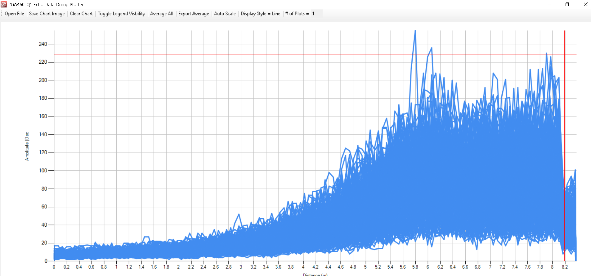
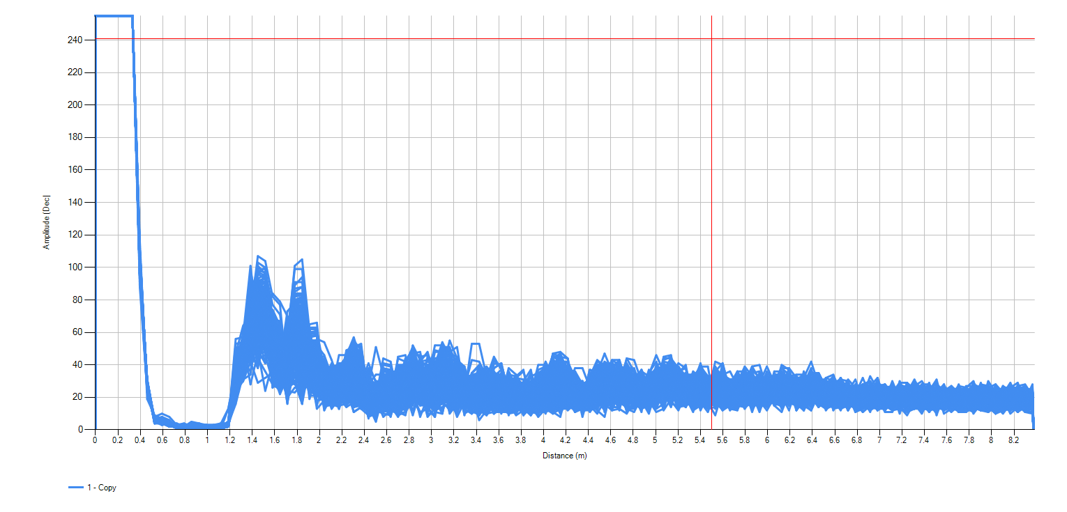
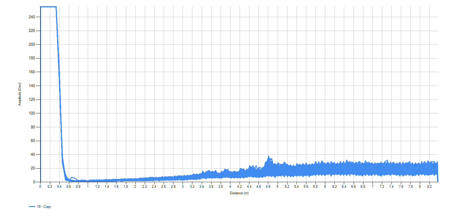
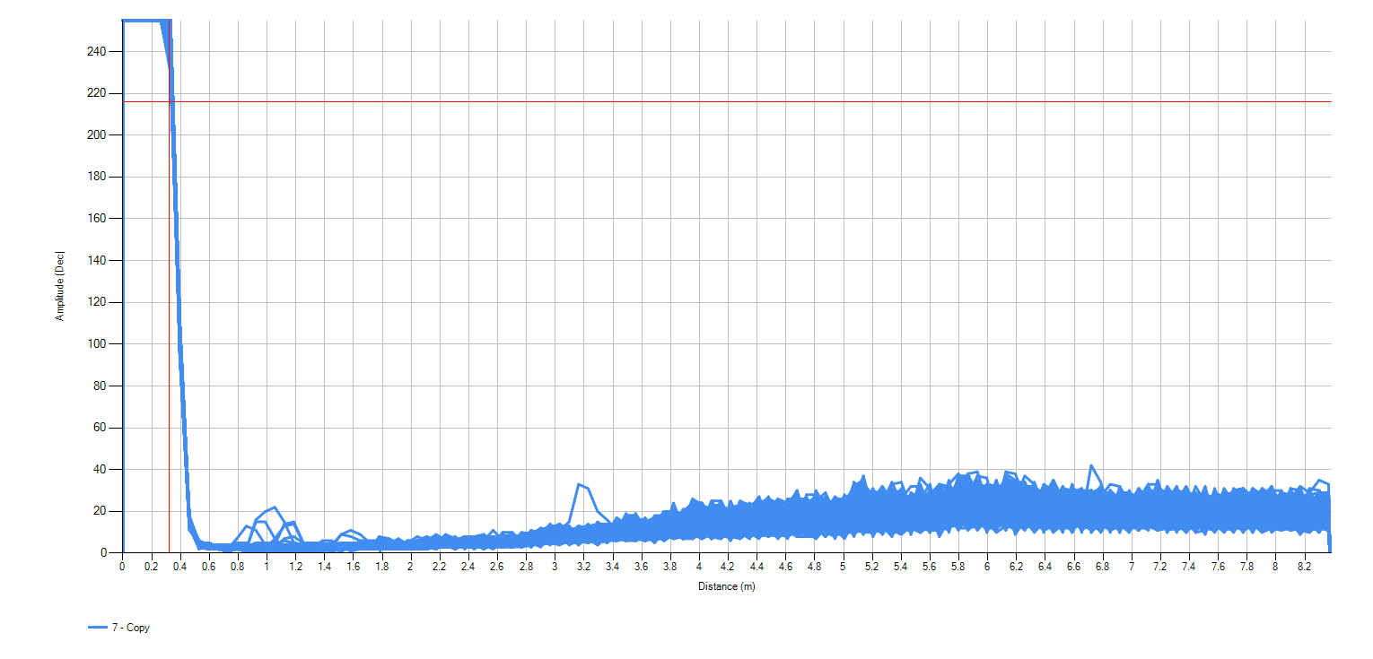
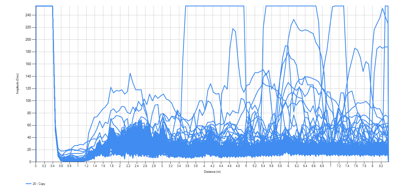
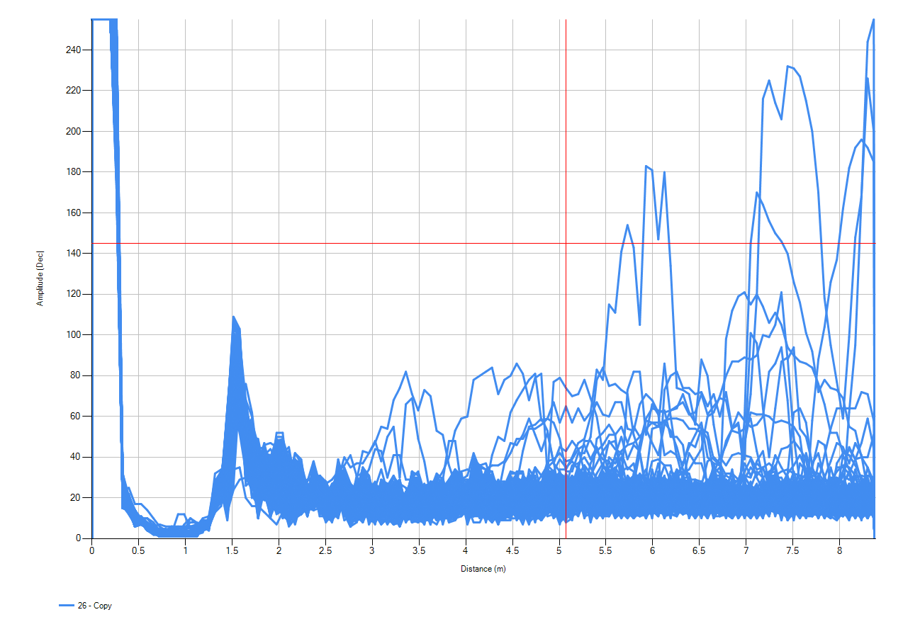
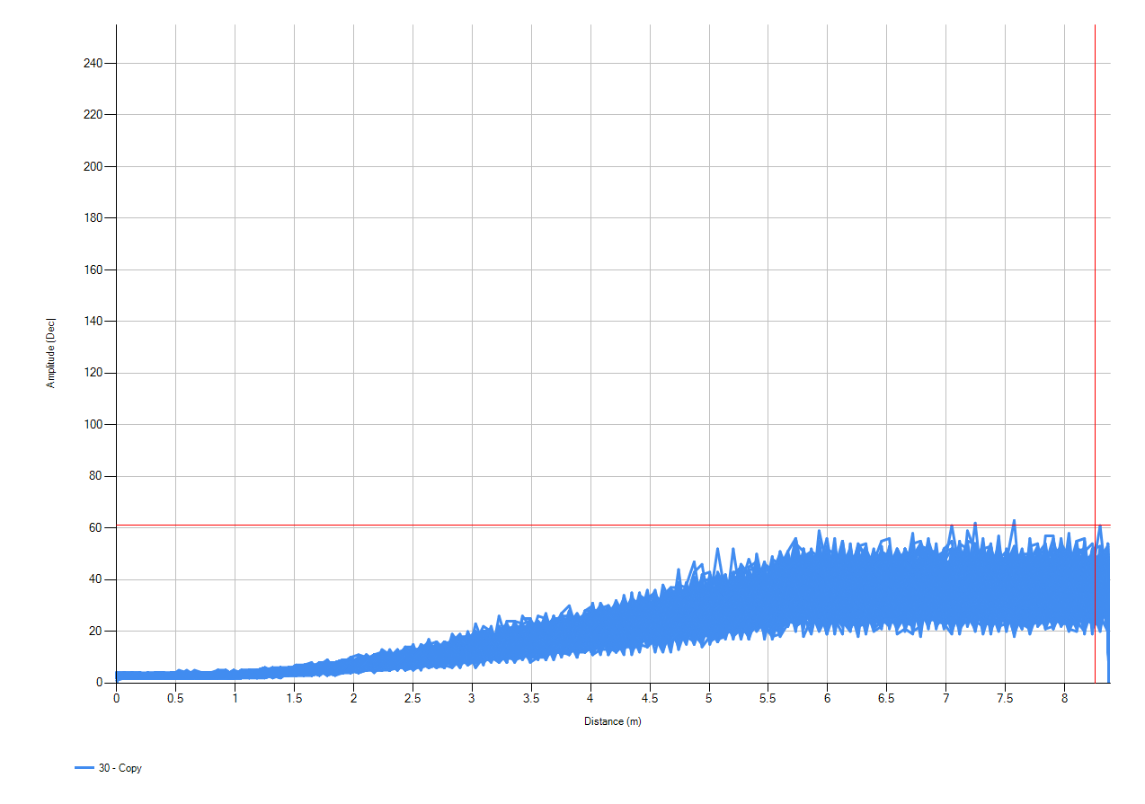
2.) Received waveforms are as follows:
Scan 1: This is an EDD of an empty Burst & Listen scan on P2. The detection at approx 1.5 Meters is the ground below. The system was positioned in an open area with no object around it for at least 15 meters on facing side. There are no sources of noise like motors, machines or other ultrasonic sensors (to the best of our knowledge)
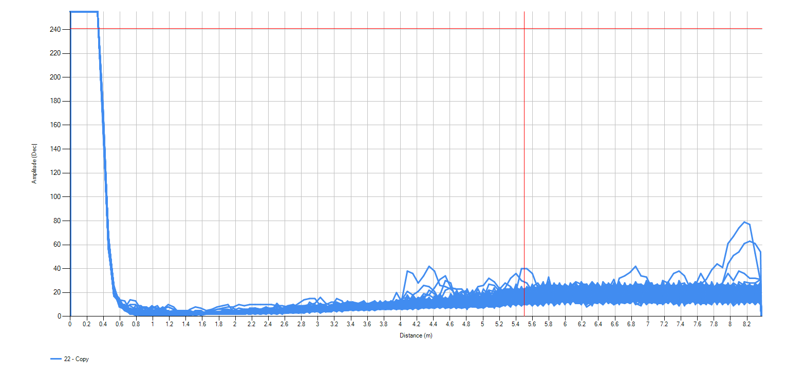
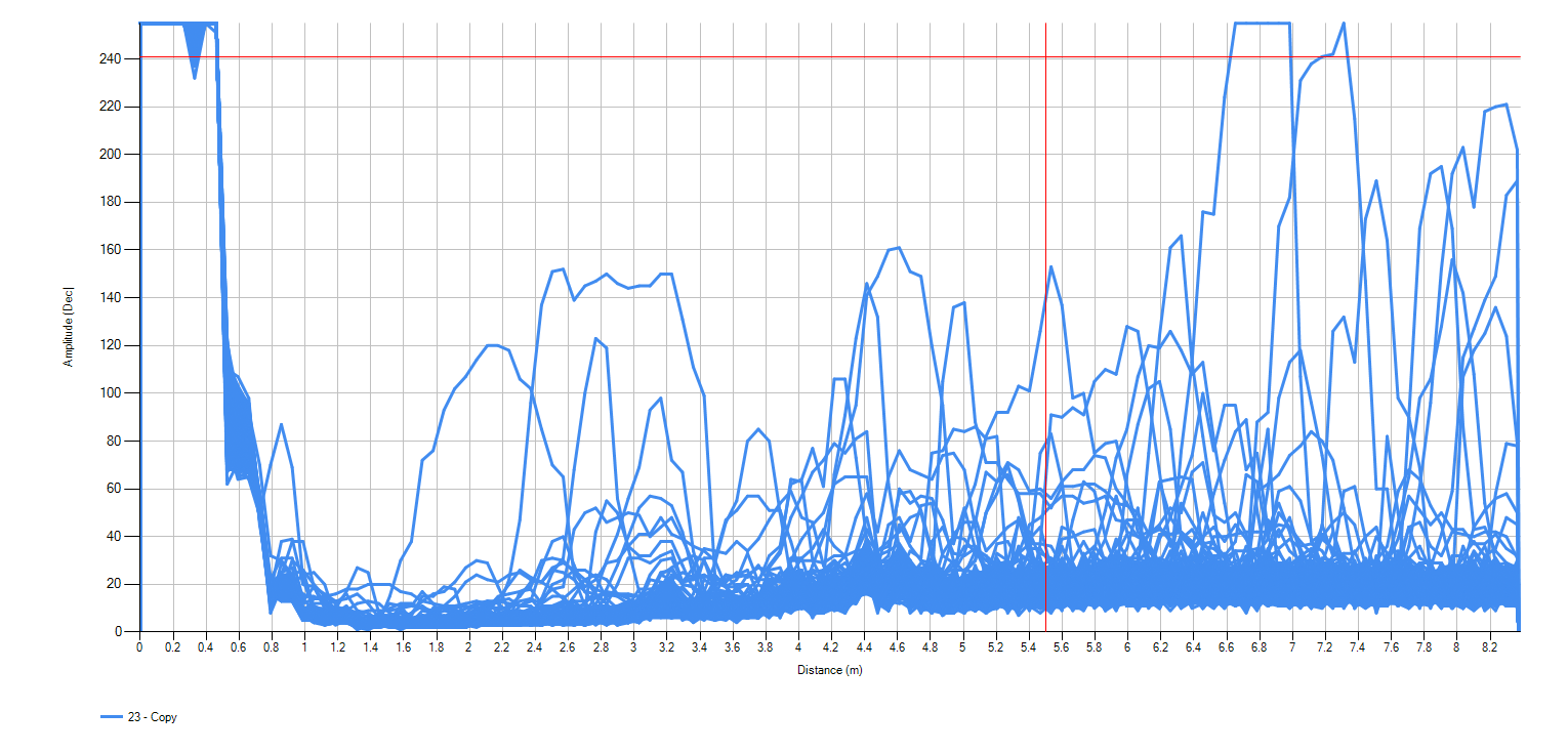
Scan 2: Is an EDD LISTEN Only scan with the XDCR+ connected to GND in the same exact position.
The noise seen in scan 1 makes it difficult for us to set thresholds that will give us reliable detection and eliminate False Triggers.
Any help in eliminating the noise source would be much appreciated.
Please let me know if it is possible to have our PCB design reviewed by a TI engineer.
Thanks & Regards,
Yash Darad