This thread has been locked.

If you have a related question, please click the "Ask a related question" button in the top right corner. The newly created question will be automatically linked to this question.

IWR1642: IWR1642

Part Number: IWR1642

Hi dear 

1. Before making antenna PCB, we would like to make two saperate board such as  Antenna board and main board. Is it feasible to saperate antenna from main board? I guess there would be a heavy signal path loss. If possible , how to?

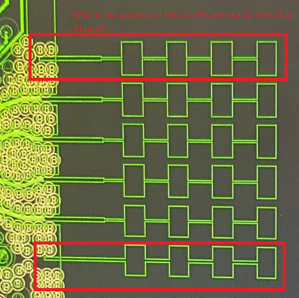
2. What is the reason for the red rectangled part two antenna? It looks like connected to GND.

  • [1] Technically its' feasible, you need design the transition from the mm-wave IC board into Antenna board. You could explore options such as WR12 waveguide transitions or transition into 1 mm co-axial connector and then interface with Antenna board.

    These solutions could be applications specific. Cost, Complexity of the system, Signal loss performance trade-offs and reliability and volume manufacturing trade-off may need to be considered. However TI doesn't have any reference solution for this, you may have to explore by yourself.
    Simplistic approach is to keep antenna and MMIC on the same board.

    [2] These are dummy antennas, they are kept to reduce the mismatch between the 4 receive antennas.
    This will help us to improve parasitic matching on the inner receiver antennas (RX2 & RX3) as compared to outer antennas RX1 and RX4.
    These dummy antenna elements help in slight gain/ phase mismatch reduction.

    Thanks and regards,
    CHETHAN KUMAR Y.B.