This thread has been locked.

If you have a related question, please click the "Ask a related question" button in the top right corner. The newly created question will be automatically linked to this question.

FDC2212: Sensor Design

Part Number: FDC2212
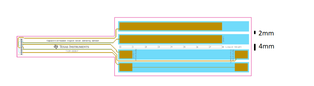
Other Parts Discussed in Thread: TIDA-00317, FDC1004

Hello;

I am trying to deisgn level sensor with fdc2212.

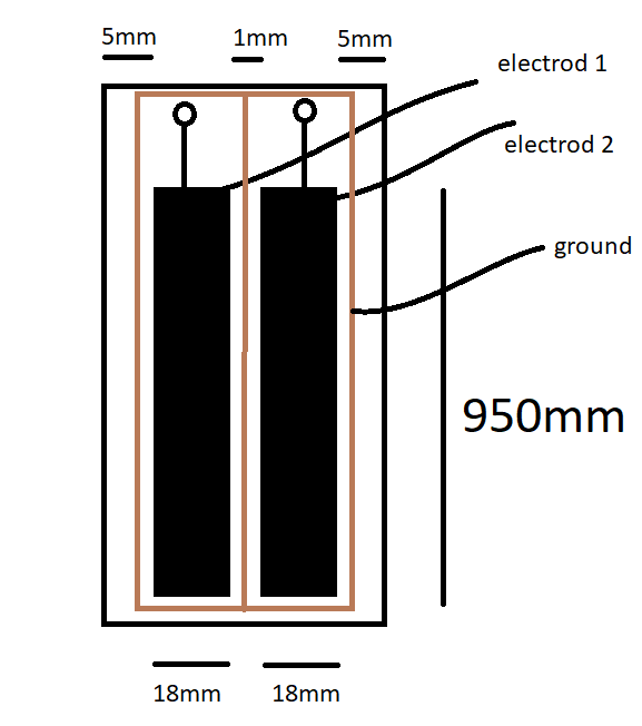
I have a FDC PCB, an PCB elecrod to use meuasre capacitive which have two cu plane and  aluminium encloser. Aluminium has grounded. PCB electrod and FDC PCB is stable in Aluminium encloser.
FDC PCB also in aluminium encloser. I use single ended sensor configuration to measure capacitor of PCB electrod.

L CMH series 22uH, C 100pF NPO, RCOUNT=0XFFFF,  SETTLECOUNT= 0XFFFF

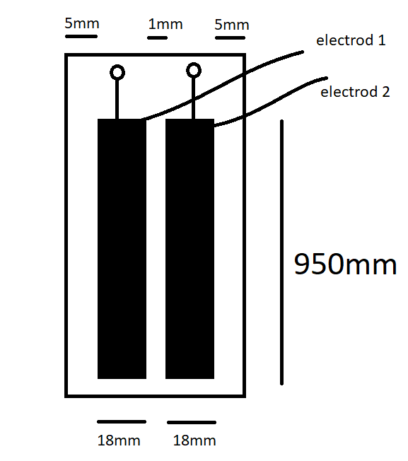
PCB electrod is shown above. When I connect to IN0A to electrod 1 and IN1A to electrod 2 on auto scan conversion mode, capacitor value is 72pf and 70pF respectively.

But  When I connect to IN0A to electrod 1 on single conversion mode, capacitor value is 75pf ,  When I connect to IN1A to electrod 2 on single conversion mode, capacitor value is 75pf.

*Electrods effect each other, How I cancel this effect?

*Is 1mm distance between electrods enough?

What is your offer for sensor design?

Best Regards.

  • Why are you measuring both electrodes? Normally, you would ground one of the electrodes and measure the capacitance of the other.

    The unused channels are connected to ground, but there could be some resistance. If the electrodes are not supposed to interact with each other, then they should be spaced further apart.
  • Hello;

    There are grounded aluminum encloser. Two alectrods are used to find liquid slope.

    " When I connect to IN0A to electrod 1 on single conversion mode, capacitor value is 75pf , When I connect to IN1A to electrod 2 on single conversion mode, capacitor value is 75pf."

    This test has done becauese some measurement error when I use auto scan conversion.
    I see that when FDC auto scan mode, ch2 to measurement is change 70 to 72pF.
    I think the oscilation of chanels interact echother.

    When Auto scan conversion is on, FDC switch between channels and unused chanel eloctrodes are not oscillate next time properly.

    What is the reason of this?

    When auto scan mode is use how many distance may be between electrodes to proprely measurements on single emded sensor confuguration?

    Best Regards.

  • Hello;

    İf I build an ground on PCB like below picture. Do  interacting betweeen electrods reduce?

    There are one more ground which is aluminium encloser.

    Best Regards.

  • Hello;

    I find out TIDA-00317 design for level sensor with FDC1004 .

    There are three electrods which are level, environmental and referance part. The distance between referance and level part is 4mm.

    But FDC1004 is a little bit different from FDC2212. 

    Is 4mm enough for FDC2212 to not interract  electrods eachother?

    Is oscilation frequency impact this distance?

    Best Regards.

  • The farther apart you can space the electrodes, the better. Also, larger sensors need to be spaced farther away from each other to avoid interaction.

    If the same device is driving both electrodes, then the interference should at least be consistent (since they will not both be actively driven at the same time). It could be something that you can compensate for.