This thread has been locked.

If you have a related question, please click the "Ask a related question" button in the top right corner. The newly created question will be automatically linked to this question.

FDC2114EVM: Settle Count

Part Number: FDC2114EVM
Other Parts Discussed in Thread: FDC2114, FDC2214, FDC2214EVM,

Dear TI

Here are my questions:

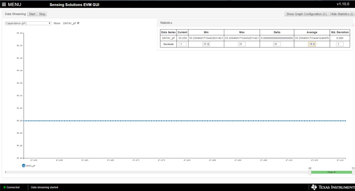
1. Currently, we are evaluating the "FDC2114 IC" because it has a high sample rate which is suitable to our design. I noticed that its delta without target is totally zero. Does it normal? Please see figure below.

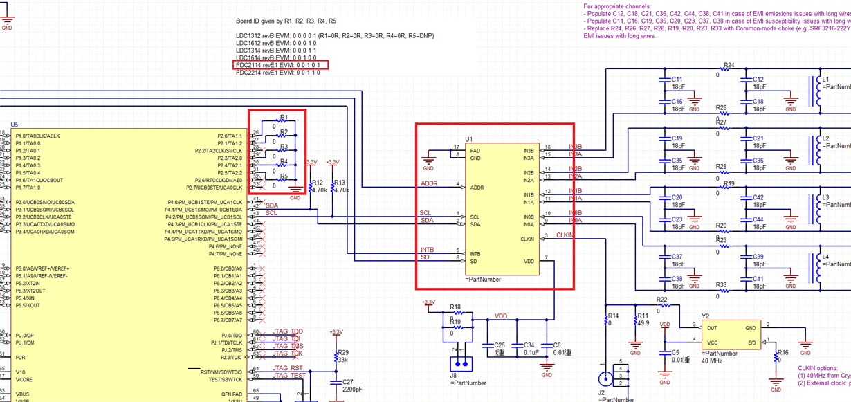
2. Does  the set up correct? I am using the FDC2214 EVM and changed the FDC2214 IC into FDC2114. I also changed the resistor position as what instructed in the schematic diagram. Please see figure below.


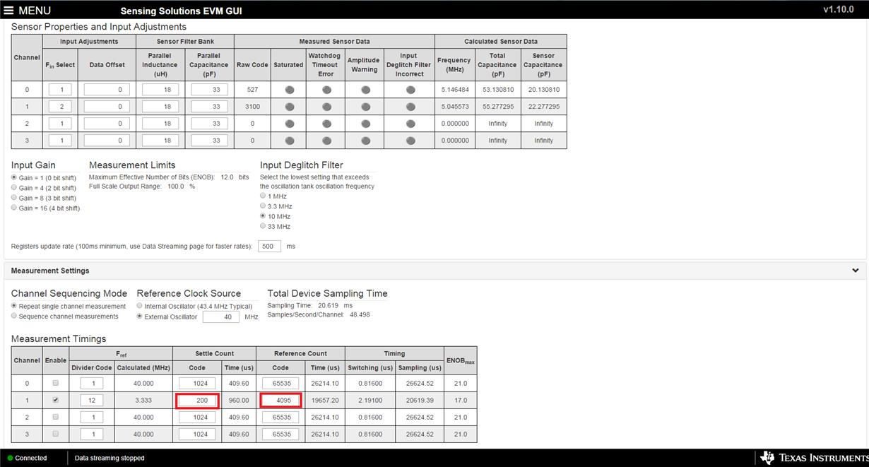
3. For FDC2114, what would be the settle count value  and Rcount value if i use 3 channels?

Thank you.

Best Regards

Janine Lin

  • Hi Janine,

    1. This is normal behavior for the FDC2114 because it is lower resolution than the FDC2214. The FDC2214 can detect more subtle shifts in sensor frequency, which means that it also detects more noise than the FDC2114.

    2.The FDC2214EVM and FDC2114EVM have identical schematics. There should be no difference in any of the resistors. The only difference is which device is populated in the FDC's footprint.

    3. The settle count and Rcount values can be configured for each individual channel. You should configure them so that they meet your desired resolution and sample rate. Please see section 9.3.2 for more information about the timing of multi-channel operation.

  • Janine,

    With the FDC2114 you have to be more careful about saturation. This is what the gain settings are for. It is easier to tell if you are saturated by looking at the raw code instead of the calculated capacitance.

    Settle count and RCOUNT work the same way as the FDC2214.

    You updated the EVM firmware as well, correct? Does it say that the FDC2114EVM is connected?
  • Thank you Kristin.

    For answer #2, you mean FDC2214 and FDC2114 footprint are different?
  • Thank you Clancy.

    1. Gain is always 1, if i choose Gain 4 it is saturated . The LC tank value (18uH)(33pF), Fin = 2 , Fref = 12 , Settle count 512 , Rcount 4095 , External
    Osc 40 Mhz.


    2. I did not update the firmware, it automatically connected to GUI "SSP EVM connected - FDC2114".

    Clancy, how to tell if it is saturated by looking at the raw code? Thank you.

  • Dear Clancy and Kristin


    When to you use a data offset?

    Thank you.
  • Hi Janine,

    1. The FDC2214 and FDC2114 are pin-to-pin compatible.

    2. The gain setting allows you to control the step size (the number of codes) of your LSB. If you have a high sensor frequency but a very small response to the target, using higher gain values will allow you to see the full response from your target. However, the MSB may not be large enough for the FDC2114 to output the correct output code to represent your high sensor frequency. You can use the offset to compensate for this.

    Best Regards,
  • Thank you Clancy.