This thread has been locked.

If you have a related question, please click the "Ask a related question" button in the top right corner. The newly created question will be automatically linked to this question.

FDC2114EVM: range

Part Number: FDC2114EVM
Other Parts Discussed in Thread: FDC2114, FDC2214

Dear Clancy and Kristin

I observed as the time increases as well as the sensing range of FDC2114. 

Is this a normal behavior of this device?

I used 3 channels. This is the configuration setting of GUI.
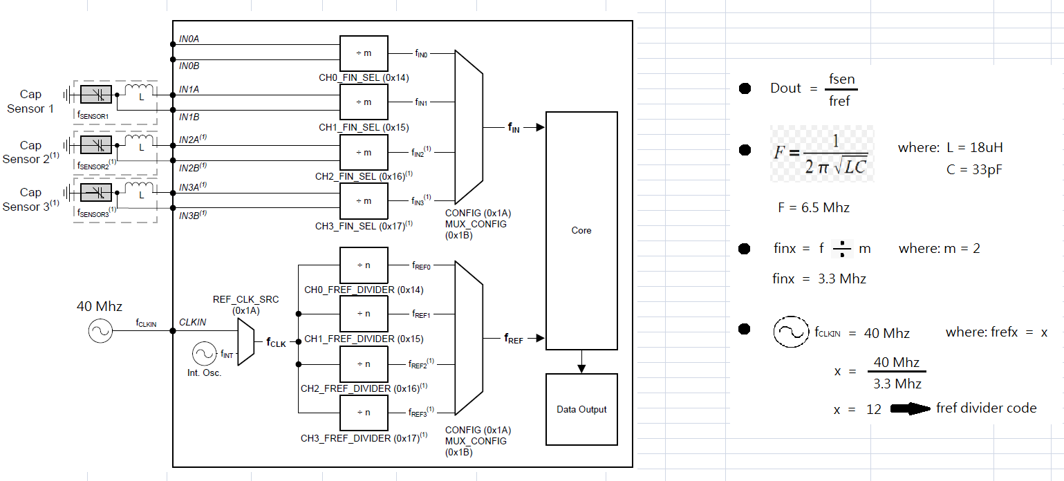
Fin = 2 , 

Parallel Inductance = 18 uH

Parallel Capacitance = 33 pF

Input Gain = 1 (0 bit shift)

Input Deglitch Filter = 10 Mhz

Fref = 12

Settle Count = 512

Reference Count = 4095

Idrive Code = 17

  • Hi Janine,

    Do you mean that increasing the measurement time (RCOUNT) increases the sensing range of the FDC2114? If so, this is normal behavior for the device. The longer you give the FDC2114 to make its sensor frequency measurement the smaller the frequency shifts it can detect, which corresponds to weaker target interactions at longer distances.

    I notice that your Fref is set to 12 MHz. Your resolution will significantly increase if you use the maximum Fref (40MHz for multi-channel operation).

    Best Regards,
  • Dear Kristin


    12 is a fref divider code. I am using the maximum RCOUNT already, its FFF = 4095.

    What i mean is when i close my hand to sensor its 2 cm at first. After 3 minutes, when my hand close sensor becomes 3 cm.
    Is this a normal behavior of a FDC2114?

  • Hi Janine,

    What is your reference frequency? An fref divider code of 12 is extremely high.

    Can you also clarify what your test setup is? The detection range for the FDC2114 should not change unless the environment changes or some of the FDC2114's register values are changed.

    Best Regards,
  • Dear Kristin

    1.  My reference frequency is 40 Mhz.

    2. I am using 3 channels, Ch1 for proximity sensing and Ch2 and Ch3 for touch buttons.

    3. This is how i get the fref divider code.  

  • Hi Janine,

    Your reference frequency should be much faster than your sensor frequency. Fref (after the Fref divider) should be at least 4 times larger than Fin (after the Fin divider). You can find this information in Table 1 of the datasheet.

    For your 3.3 MHz Fin, your Fref should be at least 13.2 MHz after the divider. However, the higher the reference frequency is the better your resolution and accuracy will be. You should use the 40MHz reference frequency with a divider of 1. Currently you have Fref set to the same frequency as your sensor frequency, which will give you very inaccurate readings and could explain the odd range behavior you observed.

    Best Regards,

  • Dear Kristin

    Does it mean i set the wrong parameters? In GUI. Fin can set either 1 or 2.

    In datasheet its says "the digitized output for each channel is proportional to the ratio of fSENSOR/fREF ". Does it mean fsensor and freference must be the same?

    Please guide me I am confused. I used 3 channels with an external oscillator of 40Mhz. If i have a LC tank of (18uH)(33 pF) for each channel what would be the parameters ?
    How about if the LC tank is (56uH)(33pF) or (100uH)(33pF), what will be my Fin , fref divider code , settle count and Rcount?

    Thank u

  • Hi Janine,

    You may set the Fin divider to either 1 or 2 for your sensor frequency. This is not set incorrectly.

    Fsensor and Fref should absolutely not be the same. The equation below is taken from the FDC2114's datasheet:

    The FDC2214 has 28 bits to output any possible sensor frequency between 1kHz and 10MHz. If Fsensor = Fref, then Fsensor/Fref = 1, and the minimum sensor frequency that DATAx can represent is 2^12. Fref needs to be at least 4x larger than Fsensor for the DATAx equation to work and to maintain reasonable resolution.

    Also note that whenever the capacitance of the sensor changes, Fsensor will change in response. Even if you set Fsensor equal to Fref initially (which you should not do), they would not stay equal to one another.

    With L=56uH and C=33pF, your sensor frequency would be ~3.7MHz. Using equation (1) from above and assuming your Fin and Fref dividers are set to 1 and Fref = 40MHz, the FDC2114 would output 378 (in binary). Note that this is assuming that the total capacitance in the LC tank is 33pF. If 33pF only included the surface mount capacitor in the LC tank, the additional sensor capacitance would change the sensor frequency and result in a different output code.

    With L=100uH and C=33pF, your sensor frequency would be ~2.771MHz. Using equation (1) from above and assuming your Fin and Fref dividers are set to 1 and Fref = 40MHz, the FDC2114 would output 283 (in binary). Again, this is assuming that the total capacitance in the LC tank is 33pF. If 33pF only included the surface mount capacitor in the LC tank, the additional sensor capacitance would change the sensor frequency and result in a different output code.

    Fin = Fsensor/(Fin divider code)

    The Fref divider code, Fin divider code, settlecount, and Rcount values are all user controlled in the FDC2114's registers. You can use page 17 of the datasheet to determine your settlecount and Rcount values. Use 1 for the Fref divider and either 1 or 2 for the Fin dvider.

  • Dear Kristin


    What's the purpose of Fref divider? Why there are choices from 1 ~ 1023 and when i can set this value?
    Thank you.
  • Hi Janine,

    The purpose of the Fref divider is so you can use an external clock that is faster than the 40MHz maximum Fref. Fref should always be as high as possible without exceeding 40MHz after the Fref divider.

    Best Regards,