This thread has been locked.

If you have a related question, please click the "Ask a related question" button in the top right corner. The newly created question will be automatically linked to this question.

LM73: NACK on Write

Part Number: LM73

I'm experiencing a strange behavior I can't explain. I have a product that has an LM73 in it. I communicate with it using an FTDI USB device on which I bit-bang the I2C/SMBus interface. When polling the device I always read the status/control register to insure it has the resolution setting I want to use.

On my test bench this works great. I can write the register address, do my repeated start and read the register.

When I move my unit into the temperature chamber I experience a strange behavior. If I address the LM73 for a read, it ACK's and provides the temperature data as the pointer register is 0 at startup. If I address the LM73 for a write however, it NACK's the address.

I used a scope to capture the communication waveforms to see if I could see the issue. It made me realize I was mistakenly using a 5V controller on my bench instead of the 3.3V I'm powering the LM73 with. Because of this I went ahead and tried the 5V cable in the chamber, hence why all these use 5V(Also helps clarify that the LM73 is pulling the line high, not the controller by mistake).

Here is the successful read of the control/status from the bench (Top - SDA, Bottom - SCL):

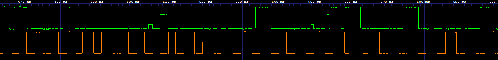
And the failed one from the chamber (it tries a couple more times after that):

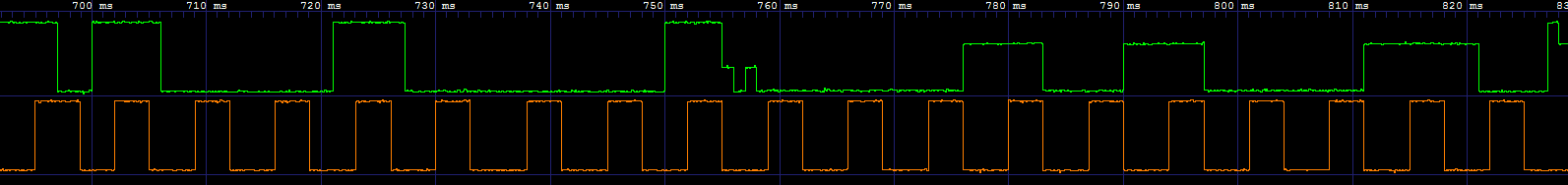
And just a quick peek at it working for a read in the chamber (from later in the above capture after it gave up on the control/status byte)

This strange behavior of ACKing a read but not a write has me stumped. If it didn't work at all then I would know it's a connection, voltage drop (the communication wires are much longer in the chamber) or timing issue (the chamber computer does the bit-bang slower as you can see above) but if it were any of those a read wouldn't work either. Does anyone have any insight on what might be happening?

  • Dear Joseph -
    From what i can see on your captures -
    the first one looks like the address of the device (from a software perspective) is a 0x48h, as I can clearly see the start condition, followed by 10010000b, which equates to a 0x90, which is correct if the 7 bit device address is 1001000 (0x48h), using an LM73-0 would be floating the address pin) and you are doing a write.

    Next I see in the 'good' sequence what appears to be some attempt of using the SDA line, but the clock appears low, so I not thinking this does anything. then a 0000 0100 (0x04h) then a 0110 0100 (0x64h) - is that what you see/intend to send, too?

    in the second sequence, I see the start, then a 101000000, which is an 0xC0, so not a correct address, then you miss several clock cycles - then another start followed by what looks to be 100100, then the image cuts off - perhaps the FTDI device is temperature sensitive - not sure - it does not look very stable - can you check that our or consider actually using I2C module inside an MCU? (not sure what your exact considerations or application requirements might be - so just some thoughts for you here)

    in the third sequence, I can see start condition again, followed by 10010001 (0x91), which is a read, followed by a 00010100 (this would be a 0x14), then 10....?

    I think the problem may lie with your I2C engine? is it possible you exposed it to the wrong voltage? did you see the notes 1 and 2 on page 2 here:
    www.ftdichip.com/.../DS_C232HM_MPSSE_CABLE.PDF
  • Josh Wyatt said:
    Dear Joseph -
    From what i can see on your captures -
    the first one looks like the address of the device (from a software perspective) is a 0x48h, as I can clearly see the start condition, followed by 10010000b, which equates to a 0x90, which is correct if the 7 bit device address is 1001000 (0x48h), using an LM73-0 would be floating the address pin) and you are doing a write.

    Yes that is correct, is an LM73-0 with the a floating address pin.

    Josh Wyatt said:


    Next I see in the 'good' sequence what appears to be some attempt of using the SDA line, but the clock appears low, so I not thinking this does anything. then a 0000 0100 (0x04h) then a 0110 0100 (0x64h) - is that what you see/intend to send, too?

    The first two parts are correct, but after the 0x04h (the control/status byte pointer address) it is not 0x64, but a repeated start, followed by the device address again (with with the R/W bit high this time). After that the LM73 transmits the control/status byte as expected.

    As for the what youre talking about in the SDA line I'm not sure which of a few things you're referring to. In order to detect an ACK, I set the SDA line high (at least from a software perspective) and change the direction of the pin. This results in the minor uptick to 1V you see before each ACK clock pulse. After the device address ACK the pin does go high. I don't know why this happens, but I do know it is not the controller doing this. You can tell because it goes up only to the 3.3V level, if it were the controller it would be 5V.  I assume it's the LM73 since I don't know why other devices would be manipulating the line but I can't be sure. After the device ACK's the the 0x04 something on the bus (again I assume the LM73) drives the line to 3.3V, then I change the direction of SDA to output which drives it low very briefly before I set it high to prepare for the repeated start.

    Josh Wyatt said:

    in the second sequence, I see the start, then a 101000000, which is an 0xC0, so not a correct address, then you miss several clock cycles - then another start followed by what looks to be 100100, then the image cuts off - perhaps the FTDI device is temperature sensitive - not sure - it does not look very stable - can you check that our or consider actually using I2C module inside an MCU? (not sure what your exact considerations or application requirements might be - so just some thoughts for you here)

    Ops I made a mistake and scrolled back one sequency too far when taking my screen grab. This is from my utility that polls all the hardware continuously. It is trying to talk to another device (something from another model which isn't present in this system). For the LM73 it tries write three times and then gives up, does a bus reset and then reads the device to get the temperature (and assuming the lowest resolution). What you see at the end of the screen grab I did attach is the first attempt to talk to the device. Here is the sequence I meant to capture (I went ahead and grabbed all three attempts this time):

    Between each attempt I wait a bit before starting the next attempt. When the bus is inactive the clock does not pulse.

    Josh Wyatt said:


    in the third sequence, I can see start condition again, followed by 10010001 (0x91), which is a read, followed by a 00010100 (this would be a 0x14), then 10....?

    You've forgotten the ACK pulse, it's a 10010001 (0x91), ACK (from LM73), 00101001 (0x29 - driven by the LM73 because it's at 3.3V), ACK. As the LM73 has not accepted any write the pointer register is 0 so this is the first byte of the the temperature data. The second byte transmits the same as the first so I didn't feel the need to include it in my capture. The first byte here translates to 42C which is right for this application.

    Josh Wyatt said:

    I think the problem may lie with your I2C engine? is it possible you exposed it to the wrong voltage? did you see the notes 1 and 2 on page 2 here:
    www.ftdichip.com/.../DS_C232HM_MPSSE_CABLE.PDF
    It seems unlikely. We have used this system for years to communicate with dozens of devices (digital potentiometers, EEPROMs, DACs, ADCs and other temperature sensors). It's been in place longer than FTDI has offered their MPSSE style cables that have I2C/SMB functionality built in (hence why I'm bit-banging it using a TTL-232RG-VSW3V3-WE/TTL-232RG-VSW5V-WE). We have several different test systems that use this hardware and software so changing the communication hardware would be a major hassle. We've investigated switching to the MPSSE style cables several times but found the cost of adapting our systems to be too high to warrant it unless absolutely necessary.
    While I can't rule out that this device simply can't do the job I can confirm it is not a faulty FTDI cable as we have them stocked and I have tried multiple.
  • Dear Joseph -
    What is your pullup resistor on SDA line? Looks like the LM73 is trying to ACK it, but is not able to pull the line down (this device cannot drive the line high, so something is responsible for that)
  • It is a 10k resistor. I'm more of a software person and my knowledge is weak on the electrical aspects of this, but why would it be able to pull the line low when to ACK a read, but not a write?

    Looking back at the waveform I sent before I notice that the failed attempt to talk to the device not present never finished the attempt with a stop. I don't think it's likely but that is something to investigate that I'll tinker with this afternoon.

  • Joseph -
    Great - I saw in this document that the USB to I2C cable needs some special handling (two pins are tied together for SDA line and WRT to making the device go back to "open drain" / set to input when not driving the lines...from pages 8, 11 and 18 here:
    www.ftdichip.com/.../AN_255_USB to I2C Example using the FT232H and FT201X devices.pdf

    which then points to here: www.ftdichip.com/.../AN_113_FTDI_Hi_Speed_USB_To_I2C_Example.pdf

    They recommend pullup resistors of 10kOhms for 100kHz communications - so perhaps you will find the solution inside the software.

    If that does not lead to the answer, then we can have a closer look onto your schematic.

  • That is not the implementation we used. That implementation uses MPSSE to queue up the I2C protocol into the FTDI device. MPSSE was introduced in 2010 and this software has been in use since 2008.

    Our software is implemented using Asynchronous Bit-bang mode. It's actually built using a hardware abstraction layer that implements the I2C protocol with a class that calls methods like SetDataDirection(bool), SetData(bool) and SetClock(bool) on another object which can be changed depending on the hardware used. It was originally written to do this with parallel port but around 2007-2008 computers with those were becoming more rare, so we implemented control using the FTDI chip cables (I think that might be the first code I wrote at this job). The only downside we've seen from this implementation is speed. It's much slower to do the control this way due to the overhead of the FTDI drivers and 100kHz has never been achieved. The above screen grabs look like about 150Hz. As the I2C protocol allows for slower speeds and we don't need a very high polling rate this has never been an issue. I don't think it's the issue at play here as the speed is the same on my bench as it is in the chamber (within 5%).

    As I understand it the reason for tying two pins together for the MPSSE implementation is that the pin direction cannot be changed while a batch of commands are being executed at the chip level. Since my operations are done on the higher abstraction layer I can change the direction mid operation, eliminating the need to tie two pins together.
  •  looking at the http://www.ti.com/product/LM73   pdf

    on page 16 it says the temperature register is read only

  • That is correct, I am trying to write/read the control/status register. On page 13 it outlines that on a write you must include the pointer register. Unfortunately the LM73 is NACKing before I can send that pointer so it can't be a case of that pointer being pointed to an unwritable address.

  • OK

    So the nack happens when you try to write to control/status register.  Lets say that the pointer register was still pointing to the temperature register.  You say that you are polling the control/status register and also reading the temp register.back and forth.

    The temp register and the identification register are the the only two "read only" data registers.  

    Is there a way to test that the pointer register is truly pointing to the control /status register before the write?

  • Hello Joseph,

    Looking at the screen capture, there is one thing that is a bit concerning. In the read transaction as seen in the chamber, the High from the LM73 does not go up all the way to the supply. It seems that there is a active low driver on the bus, which the LM73 is trying to work against.

    1, Can you isolate the read to LM73 only and not to any other device on the bus?
    2. Can you use a scope with voltage units, so that we can better understand the issue?
    3. To clarify, the LM73 is working on a 5V supply with a pull up of10 K on the SMBCLK and SMBDAT to 5V as well?
  • Mark Skramstad said:
    Is there a way to test that the pointer register is truly pointing to the control /status register before the write?

    I think you misunderstand how the pointer register works. It does not matter where the pointer is before a write starts as the first byte of a write sets the pointer. If it worked as you described you would never be able to set the pointer and only the temperature data would be accessible. In these examples all I've tried to do so far is set the pointer and haven't even gotten far enough to try to actually set one of the registers.

    Amit Ashara said:
    Hello Joseph,

    Looking at the screen capture, there is one thing that is a bit concerning. In the read transaction as seen in the chamber, the High from the LM73 does not go up all the way to the supply. It seems that there is a active low driver on the bus, which the LM73 is trying to work against.

    The LM73 will not go all the way to 5V as it is powered on 3.3V. My FTDI device for those captures was a 5V FTDI device. I was using a 3.3V device in the chamber to match the supply, but realized I had been using the 5V device on the bench by mistake and switched the device on the chamber to see if that would resolve the issue.

    Amit Ashara said:
    1, Can you isolate the read to LM73 only and not to any other device on the bus?

    Unfortunately, these units are assembled elsewhere and arrive here as sealed units. I've had this thought as well and have been trying to get an unsealed unit but the powers that be have yet to provide me with one. I'm also considering rigging up a board from another device to have an LM73. I actually wasn't sure what else was on this bus, so I checked the schematic and the only other device on there is a CAT24C02.


    Amit Ashara said:
    2. Can you use a scope with voltage units, so that we can better understand the issue?

    The scope recorded voltage units, the software I used to view the waveforms (GTKWave) does not show them on the plot. I just tried to attach the VCD file showing the waveform but apparently the file type is not accepted. So I've just changed the extension to txt (VCD is plaintext anyway) so if you want to open it with GTKWave you'll need to change it back. I can attach more of these for various things I've tried if it would be helpful.

    TS_5V_Chamber.txt

    Amit Ashara said:
    3. To clarify, the LM73is working on a 5V supply with a pull up of10 K on the SMBCLK and SMBDAT to 5V as well?

    No, the LM73 is powered by a 3.3V supply. Specifically the output of a LP2985-3.3 that we used to regulate the power of this unit. On the waveforms you see 5V when the lines are driven by the FTDI controller and 3.3V when the line is driven by the LM73. So the SMBCLK will be 5V and SMBDAT will vary.

    Other projects have demanded use of the chamber so I haven't had a chance to try anything since yesterday morning. I'm going to switch back the 3.3V FTDI controller and investigate the stop issue. My mistake of capturing the wrong waveform caused me to think about how the devices being addressed are different. So while the signals look the same from bench to chamber, maybe the state of the bus is different. Although I'm not positive that is the case as when I'm not using the utility and attempting a test only relevant devices are polled. It's something I can try that doesn't involve without re-inventing the wheel by rebasing on MPSSE or some other control system. With the way this thread is going I'm beginning to fear that may be the only option.

  • Another variation of this is to test the pointer register to see where it is pointing to before and after the nack

    From the PDF on LM73:

    "A write to an invalid pointer address is not allowed. If the master writes an invalid address
    to the Pointer Register, the LM73 will not acknowledge the address and the Pointer
    Register will continue to contain the last value stored in it."

    Another thing, the LM73 does not have internal pullup resistor on the data line so if you are powering the
    lm73 with 3.3 volts and the pullup resistor is connected to a positive 5 volt supply then you may have a conflict.
  • OK i will look into how the writes on LM73 are done. Im a bit rusty with I2C . Very interesting thread
  • Ok I understand now
    you say

    "
    I think you misunderstand how the pointer register works. It does not matter where the pointer is before a write starts as the first byte of a write sets the pointer
    "

    So a write requires 2 bytes. It looks like the LM73 won't read/write a data register without latching a new valid pointer address byte. It would be nice to know what the pointer address was before and after the strange NACK, to determine if the NACK was due to an invalid pointer address byte

    The LM73 needs a special pointer byte value that allows a read without latching that value.
  • In that way, a read of a data register will determine what the pointer address value was.
  • Hello Joseph,

    It would be worthwhile to remove the other device on the I2C bus (especially if there is one only) and try it with a MCU which is powered by a 3.3V rail. The FTDI chip has been around for a long time, but if the programming of the EEPROM along with is not correct, then it may be a bus contention. At the same time using an MCU will free up the limitations of performing custom experiments.

  • Since my last update I'd tried adding a stop as well as putting a what I'd been using as a reset in between each attempt write the pointer. Neither worked but I may have been doing a bus reset incorrectly.

    I decided the only option was to change my control interface. As I mentioned earlier we'd looked into using MPSSE devices and I knew we had ordered an C232HM-DDHSL-0 (which is a 3.3V device) that had been in my desk forever. I went to create a file in my system to interface only to find a file was already there. In fact I'd written 80% of it some time in 2013 and totally forgotten it existed! That interface uses libMPSSE-I2C to implement the interface. After some debugging I was able to get it functioning on my bench.

    I took that to the chamber and it worked! I went to try and take some captures and compare because I still would like to understand why my other interface didn't work since as far as I can tell it should still be a valid I2C communication. I struggled with this it wouldn't work consistently. That turned out to be software issues and not hardware related, but by the time I'd sorted that out I decided to just put my test on and try to get some actual progress on my project before I try to solve this mystery.

  • At least the LM73 works.

    Can communication with I2C be done with  Intel x86 . Was thinking about programming a UART directly with X86 assembler etc.  Is this hard or easy to do?

  • Mark -
    Please open a new thread if discussing TI devices or PM the poster if you want to continue the conversation.
    Closing this thread.
  • Joseph -
    Understood - perhaps opening another thread with captures of what you had vs. what you have working now would be a good place to start - for comparison purposes.
    You can use the + Ask a related question button (above top right second button inboard) to keep these linked.
  • I want to remind everyone that E2E is for technical support of TI solutions. It should not be used to attack or criticize others. Guidelines for posting on E2E are shown here: e2e.ti.com/.../693054

    Failure to follow the above guidelines may result in having posting privileges removed.

    We are going to edit the above thread to have the commentary removed while retaining the technical content.

    If there are any issues with the above or future interactions with another E2E user, please contact our Customer Support Center at ticsc.service-now.com/.../
    (feel free to ask to have the issue forwarded to me)

    Thanks,
    Jim Carrillo
    Manager, Online Support
    Texas Instruments