This thread has been locked.

If you have a related question, please click the "Ask a related question" button in the top right corner. The newly created question will be automatically linked to this question.

MMWAVEICBOOST: IWR6843 ISK, no console response from mmWave Demo Visualizer

Part Number: MMWAVEICBOOST
Other Parts Discussed in Thread: UNIFLASH, IWR6843ISK, MMWAVE-SDK

system details:

OS: Windows 10

SDK version: 3.1

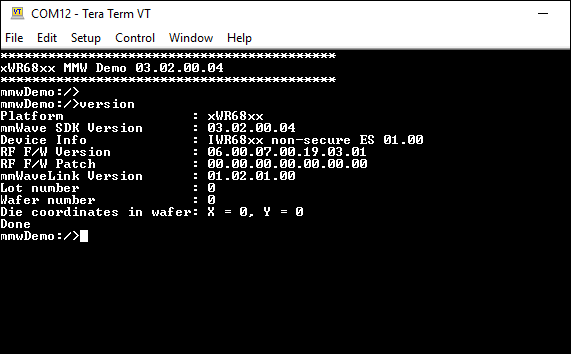
silicon revision: see image

version of compiler and code composer studio: N/A

issue:

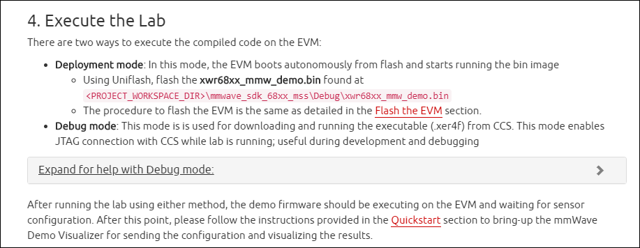
I was able to successfully flash the xwr68xx_mmw_demo.bin file located in the mmwave_sdk_03_01_01_02 folder and connect to the device in the demo visualizer (shows serial ports connected and "waiting for data ..."), but nothing happens when "send config to mmwave device" is pressed.

details:

- power was removed from the device and NRST button was pressed after flashing

- SOP2 was opened

- NERR is not lit

- NRST_FT LED is lit while the NRST button is not pressed, from my understanding of the user guide this is not correct. (user guide says "if the LED is glowing, the device is in reset state")

- if the FTDI micro-usb cable is plugged in the SOP indicator lights get much brighter and flash "randomly", eventually staying on and showing different SOP status lights than I would expect

- when connecting to the demo visualizer I've occasionally seen the message "Hardware Connected" rather than "waiting for data ..." and even more occasionally I've seen it say something like "Hardware Connected no security"
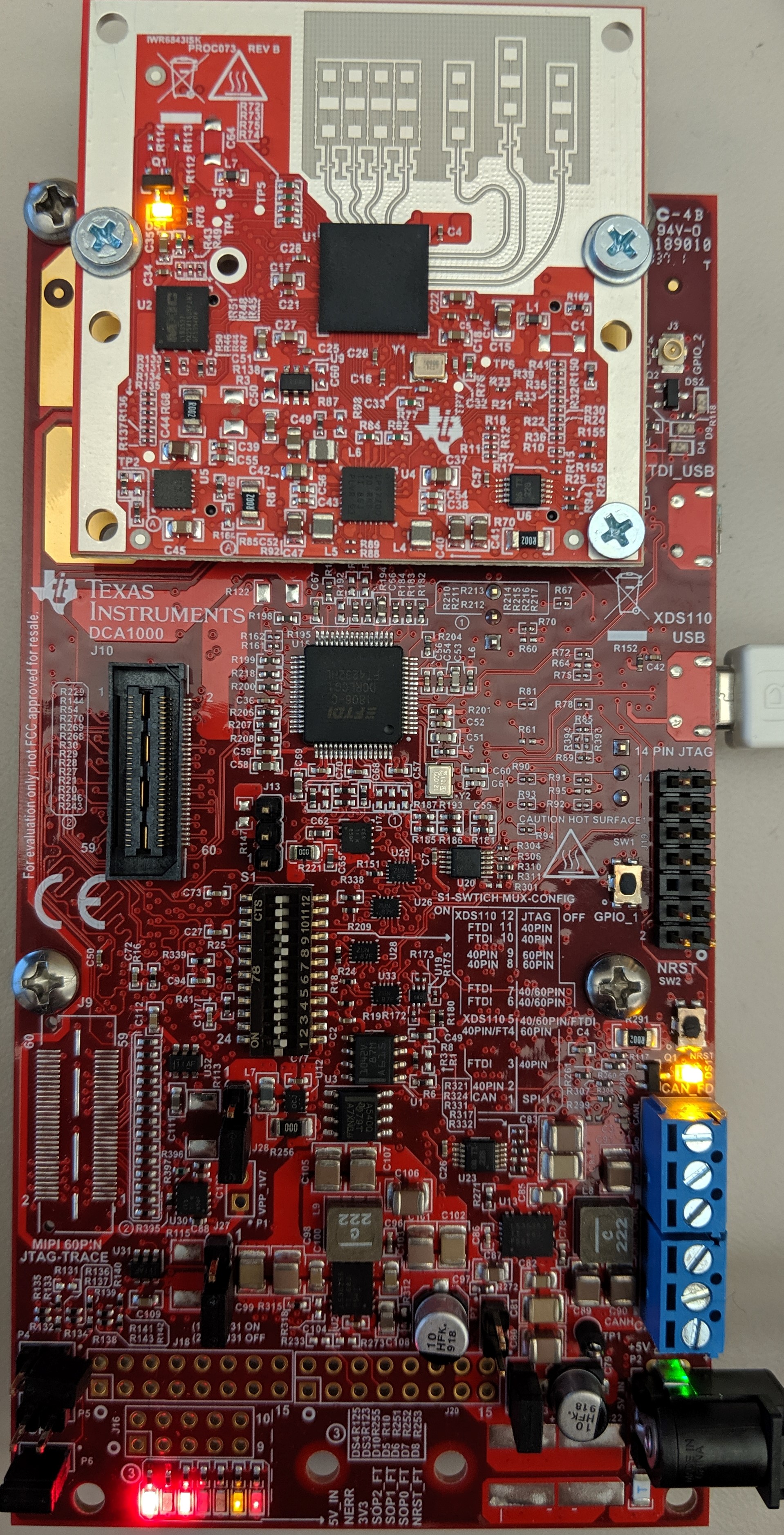
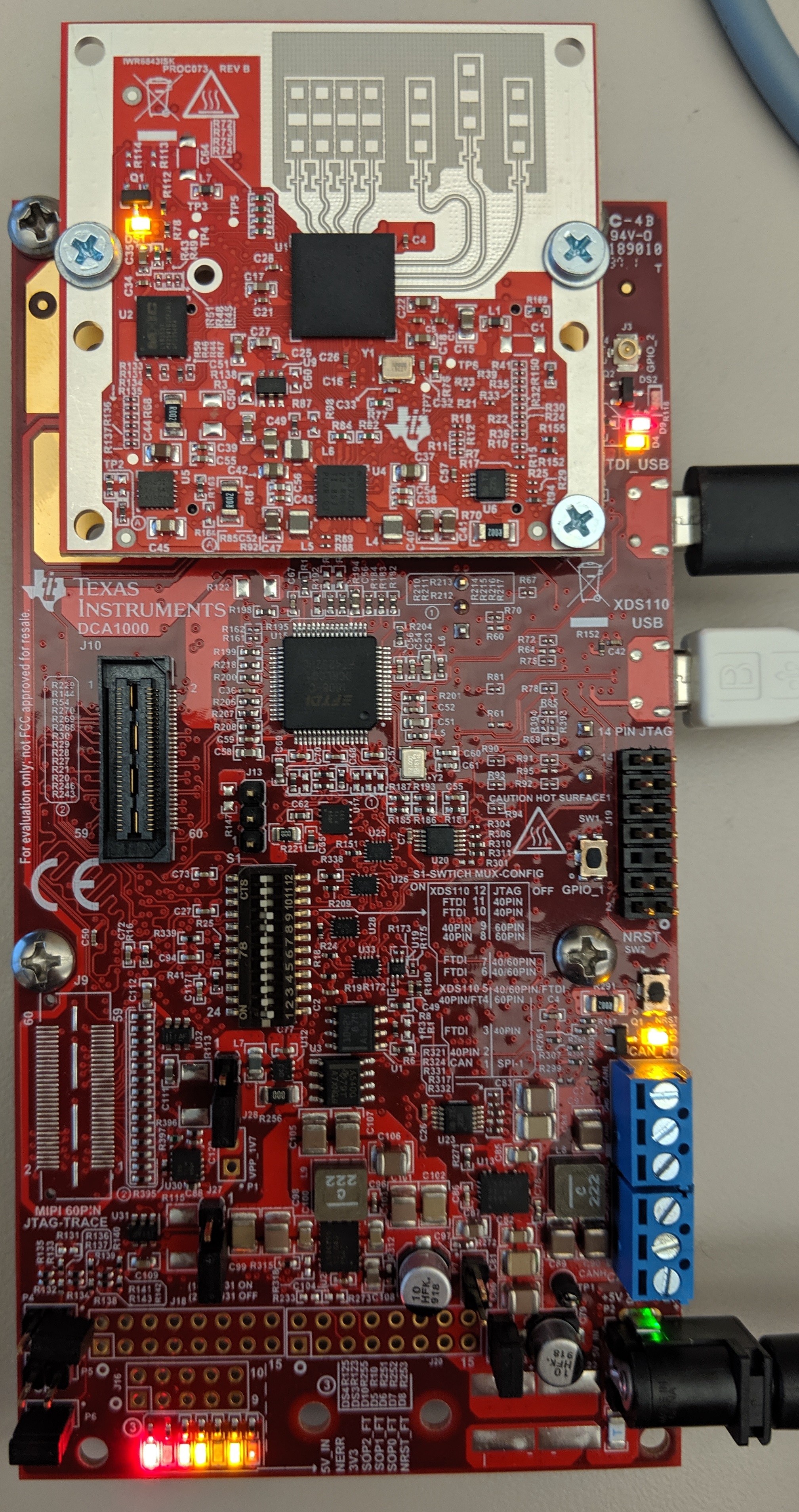
board images

board image with no ftdi cable plugged in

board image with ftdi cable plugged in

any help would be greatly appreciated, thank you.

  • Hello Nick,

    Please look at the following thread/response.

    IWR6843ISK: MMWAVEICBOOST and IWR6843ISK Unreliable

    As mentioned in item 1, the factory flashed firmware on IWR6843ISK boards has a known firmware bug so we recommend updating to SDK 3.1 which you are already doing. But as mentioned in item 2, due to a Uniflash bug, it's possible that the new image is not getting flashed leaving the board with the buggy factory image which can cause this problem. Please follow the instructions given in the linked thread to correctly flash the new binary and re-test.

    Regards

    -Nitin

  • Hi Nitin,

    some info: I currently have UniFlash version 5.0.0.2289 installed

    I tried to reflash and was met with the same result. Is there an easy way to tell what version of the SDK is currently on the board? Also, one of the links in the post you linked was broken, can you verify that all the steps below are correct?

  • Hi Nick,

    1. Please re-flash the board with the mmw demo binary provided in the latest MMWAVE-SDK (3.2.0.4)

    2. Instead of connecting the mmWaveDemoVisualizer, please connect a terminal program such as TeraTerm to the Control UART port and see if you get the mmw demo cli prompt. Use the settings shown below.

    3. The initial demo prompt (after pressing the NRST switch) includes SDK version information as shown below. You can also type the "version" command on the CLI to print out the SDK version and other details as shown below:

    Regards

    -Nitin

  • I tried that and got nothing on the serial port.

    steps:

    - reflash board with 3.2.0.4

    - try opening tera term on both Application/User UART and Aux Data Port (see settings below). nothing appears after reboot/NRST for either.

    - I tried flashing the board again and still got nothing

  • Hi Nick,

    Could you please confirm/verify a couple more things?

    1. You mentioned the following sequence in your original post:

    details:

    - power was removed from the device and NRST button was pressed after flashing

    - SOP2 was opened

    - NERR is not lit

    If you performed the steps in the above order, it is not the correct sequence. SOP2 should already be removed before you apply power (as SOP pins are  latched at boot-up time) and press NRST. So swap the above steps i.e. first remove SOP2 after flashing and then power cycle and press NRST.

    2. Ensure that your power supply is rated for atleast 3A (i.e. 5v 3A).

    3. Can you share the snapshot of your Windows Device manager , with the COM port sub-tree expanded to show the Control and Data UART ports (with the EVM connected to the PC using the XDS110 USB port).

    Regards

    -Nitin

  • 1. "SOP2 was opened" was just to let you know that I had not forgotten that step, it was done before the board was powered.

    2. power supply is rated to 5A

    3.

  • Hi Nick,

    Thanks for providing the information.  Your setup and steps you are following seem ok.

    We need to run the OOB demo in CCS debug mode on this board to understand the failure. Please follow the steps mentioned in section 3.2.2 CCS Development mode of the SDK user guide to run the mmw demo CCS binary in CCS mode and see if you get any error messages on the CCS console.

    NOTE: Before loading and running the CCS bianry, you will need to flash xwr68xx_ccsdebug.bin using Uniflash as mentioned in the above section in the user guide.

    Also, send the snapshot of the function call stack where the program failed.

    Regards

    -Nitin

  • I loaded the xwr68xx_ccsdebug.bin file using uniflash, but I don't understand the process for this at all, probably cause I've never used CCS before.

    am I supposed to:

    1. load xwr68xx_ccsdebug.bin (reboot after?)

    2. load xwr68xx_mmw_demo.bin again (I don't know what the demo CCS binary is, or at least, I can't find it) (reboot and open SOP2 after?)

    3. connect to the run configuration for the Cortex_R4/C674X/both

    4. see console output?

  • Hi Nick,

    The steps to run the demo in CCS debug mode are explained in the mmWave SDK user guide but they are also explained with visual snapshots in the mmWave SDK Demo - 68xx Lab under mmWave Industrial Toolbox on TI Resource Explorer (please use chrome as TI Resource Explorer doesn't work too well with Internet Explorer).

    1. Open the following link in Chrome Browser: http://dev.ti.com/tirex/explore/node?node=AMUtiLt8h8xgxyqc7VP87w__VLyFKFf__LATEST. This will directly take you to the 68xx SDK demo lab as shown below:
    2. Scroll down to the Developer's Guide section and install CCS 8.1 using the link in the Software Requirements table
    3. After installing CCS 8.x, scroll down to section 4. Execute the Lab, and Click on "Expand for help with Debug mode >" helpbox as shown below:
    4. Follow the instructions given in this section to run the precompiled demo firmware (location provided in the instructions) and check the console logs for any error messages.

    Regards

    -Nitin

  • Nitin,

    when I make the ccxml file and hit "test connection" it spits out this:

    [Start: Texas Instruments XDS110 USB Debug Probe_0]

    Execute the command:

    %ccs_base%/common/uscif/dbgjtag -f %boarddatafile% -rv -o -S integrity

    [Result]


    -----[Print the board config pathname(s)]------------------------------------

    C:\Users\qunhr1\AppData\Local\TEXASI~1\CCS\
    ccs901\0\0\BrdDat\testBoard.dat

    -----[Print the reset-command software log-file]-----------------------------

    This utility has selected a 100- or 510-class product.
    This utility will load the adapter 'jioxds110.dll'.
    The library build date was 'Apr 30 2019'.
    The library build time was '14:20:23'.
    The library package version is '8.1.0.00012'.
    The library component version is '35.35.0.0'.
    The controller does not use a programmable FPGA.
    The controller has a version number of '5' (0x00000005).
    The controller has an insertion length of '0' (0x00000000).
    This utility will attempt to reset the controller.
    This utility has successfully reset the controller.

    -----[Print the reset-command hardware log-file]-----------------------------

    The scan-path will be reset by toggling the JTAG TRST signal.
    The controller is the XDS110 with USB interface.
    The link from controller to target is direct (without cable).
    The software is configured for XDS110 features.
    The controller cannot monitor the value on the EMU[0] pin.
    The controller cannot monitor the value on the EMU[1] pin.
    The controller cannot control the timing on output pins.
    The controller cannot control the timing on input pins.
    The scan-path link-delay has been set to exactly '0' (0x0000).

    -----[Perform the Integrity scan-test on the JTAG IR]------------------------

    This test will use blocks of 64 32-bit words.
    This test will be applied just once.

    Do a test using 0xFFFFFFFF.
    Scan tests: 1, skipped: 0, failed: 0
    Do a test using 0x00000000.
    Scan tests: 2, skipped: 0, failed: 0
    Do a test using 0xFE03E0E2.
    Scan tests: 3, skipped: 0, failed: 0
    Do a test using 0x01FC1F1D.
    Scan tests: 4, skipped: 0, failed: 0
    Do a test using 0x5533CCAA.
    Scan tests: 5, skipped: 0, failed: 0
    Do a test using 0xAACC3355.
    Scan tests: 6, skipped: 0, failed: 0
    All of the values were scanned correctly.

    The JTAG IR Integrity scan-test has succeeded.

    -----[Perform the Integrity scan-test on the JTAG DR]------------------------

    This test will use blocks of 64 32-bit words.
    This test will be applied just once.

    Do a test using 0xFFFFFFFF.
    Scan tests: 1, skipped: 0, failed: 0
    Do a test using 0x00000000.
    Scan tests: 2, skipped: 0, failed: 0
    Do a test using 0xFE03E0E2.
    Scan tests: 3, skipped: 0, failed: 0
    Do a test using 0x01FC1F1D.
    Scan tests: 4, skipped: 0, failed: 0
    Do a test using 0x5533CCAA.
    Scan tests: 5, skipped: 0, failed: 0
    Do a test using 0xAACC3355.
    Scan tests: 6, skipped: 0, failed: 0
    All of the values were scanned correctly.

    The JTAG DR Integrity scan-test has succeeded.

    [End: Texas Instruments XDS110 USB Debug Probe_0]

    but when trying to connect to the Cortex_R4 after launching the target configuration it fails every time (see below).

  • Hi Nick,

    I have sent you a friend request. Please accept the request so that we can look into this issue over email.

    Regards
    -Nitin
  • Hi Nick,

    I'll close this ticket as this issue is being discussed offline.

    Regards
    -Nitin