This thread has been locked.

If you have a related question, please click the "Ask a related question" button in the top right corner. The newly created question will be automatically linked to this question.

LDC1612: CH0 and CH1 are increasing Trend in Frequency

Part Number: LDC1612

Hi,

I am using LDC1612 to detect a metal object near to the coil sensor.

In this module will run 24/7 application and i am getting the Digitised Frequency
value by I2C interface, based on the frequency change i am detecting the Metal object present.

At few incidence we observe the frequency captured from LDC1612 has an increasing trend without any target present refer the below image.


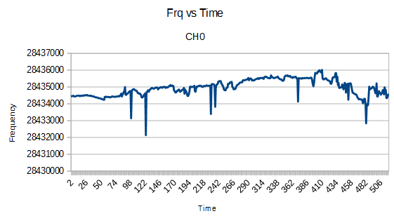
In this case we wrongly identify the condition as object detected by sensor and take further actions - which is not expected result.

What wound be the reason and how to resolve this issue?

Coil parameter values are give below:

My coil pcb sensor properties are:

Coil outer Dia : 14mm
PCB Layers : 2
Turns per Layer : 24
Trace width : 0.102mm
Spacing between traces : 0.102mm
Copper thickness: 1 oz
PCB thickness : 1.6mm

Calculated value using TI Webench Tool:
Coil inductance : 15.6uH
Sensor Frequency : 2.1MHz
Q Factor : 18.5

Best Regards,
Thiru

  • This is probably due to slow moving temperature drift. If you use a reference sensor, you should see the same pattern there. By using a reference coil, you will be able to compensate for the drift.

    The reference sensor should be shielded/have a fixed target so that if you move your normal target the reference sensor does not react.
  • We do have a temperature sensor which we use for measuring temp and compensate sensor value with a constant factor.  This still is not linear change with respect to temperature, so we are not able to determine the drifts for temp change. 

    Is there any suggestion to handle the scenario.  

    We are using the below config values as suggested through the LDC tool.

    LDC1612 Register Configuration

    Register

    Address

    Setting

    RCOUNT_CH0

    0x08

    0x1388

    RCOUNT_CH1

    0x09

    0x1388

    RCOUNT_CH2

    0x0A

    DNC

    RCOUNT_CH3

    0x0B

    DNC

    OFFSET_CH0

    0x0C

    0x0000

    OFFSET_CH1

    0x0D

    0x0000

    OFFSET_CH2

    0x0E

    0x0000

    OFFSET_CH3

    0x0F

    0x0000

    SETTLECOUNT_CH0

    0x10

    0x001E

    SETTLECOUNT_CH1

    0x11

    0x001E

    SETTLECOUNT_CH2

    0x12

    DNC

    SETTLECOUNT_CH3

    0x13

    DNC

    CLOCK_DIVIDERS_CH0

    0x14

    0x1001

    CLOCK_DIVIDERS_CH1

    0x15

    0x1001

    CLOCK_DIVIDERS_CH2

    0x16

    DNC

    CLOCK_DIVIDERS_CH3

    0x17

    DNC

    CONFIG

    0x1A

    0x1600

    MUX_CONFIG

    0x1B

    0x820C

    RESET_DEV

    0x1C

    0x0000

    DRIVE_CURRENT_CH0

    0x1E

    0x9000

    DRIVE_CURRENT_CH1

    0x1F

    0x9000

    DRIVE_CURRENT_CH2

    0x20

    DNC

    DRIVE_CURRENT_CH3

    0x21

    DNC

  • The best way to do the temperature compensation is to use a reference coil. The oscillator used for the LDC1612 is a major source of drift, so a reference coil can be used to calibrate that out. Using a separate temperature sensor will make it harder to calibrate small shifts.

    Also, are you using an internal or external oscillator for the LDC1612? Using an external oscillator significantly improves the noise and drift performance of the device.