This thread has been locked.

If you have a related question, please click the "Ask a related question" button in the top right corner. The newly created question will be automatically linked to this question.

BOOSTXL-PGA460: data monitor output from uart

Part Number: BOOSTXL-PGA460
Other Parts Discussed in Thread: MSP-EXP430F5529LP, ENERGIA, PGA460, PGA460-Q1

Hi,

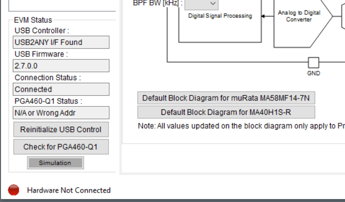
 I've MSP-EXP430F5529LP and BOOSTXL-PGA460 boards and they are working well. What I'd like to do for production is I'd like to set up my BOOSTXL-PGA460  and prepare measurement settings using MSP-EXP430F5529LP and PGA-460Q1 EVM GUI. After that, I'll burn EEPROM so that all the settings are saved. 

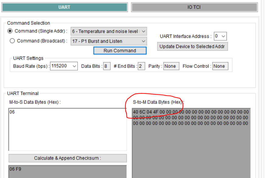
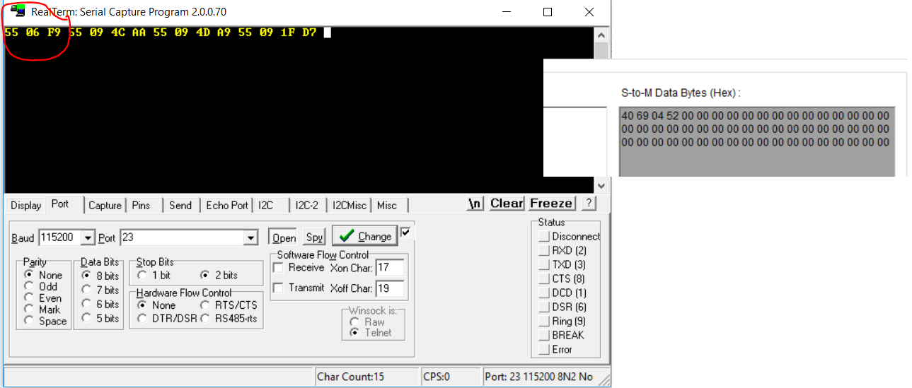
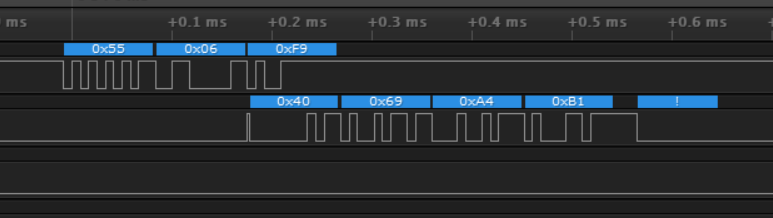
 I'll use another microcontroller and uart to send start measurement commands in listen only mode. I also would like to receive measurement data from the same uart as well. Is it possible to do it?

thanks,

  • Lu,

    I will look into your request and get back with you by Tuesday.
  • Hi Bharat,

     Any update on this? Thanks,

    Bharat Aravamudhan said:
    Lu,

    I will look into your request and get back with you by Tuesday.

  • Lu,

    Yes you should be able to using to use another MCU and UART to send a start measurement commands in listen only mode and should be able to receive the data.

    Just make sure if all the MCU used are in same logic levels.

  • Hi Bharat,
    Do you have instructions or documentation on how to run PGA460 in stand alone mode with Energia. I tried "PGA450Q1EVMS_UART_Demo" but was not able to get uart output working.

    Thanks,
  • Hi Lu,

    You may be confusing the available PGA450 and PGA460 example codes. These are different part numbers, and are not cross-compatible with one another.

    If you are using the PGA460, refer to the following documentation for the Energia implementation:
    PGA460 Software Development Guide ( www.ti.com/.../slaa730 )
    The actual PGA460 Energia source code is available as:
    PGA460 Energia Library and Code Example ( www.ti.com/.../slac741 )

    If you are using the PGA450, see the following E2E post regarding in-development status of the PGA450Q1EVMS_UART_Demo:
    e2e.ti.com/.../795854
  • Hi Akeem,
    Thank you for catching my errors. I've PGA460 and got it working now with PGA460 Energaia examples. I also was not aware that I'd need another usb to uart IC to see uart output data from PGA460 board.

    Thanks,

    Lu
  • Hi Akeem,
    I've been programming my (BOOSTXL-PGA460 + MSP-EXP430F5529LP) bundle with Energia examples (stand alone) as well as PGA460-Q1 EVM program and my board seemed to be bricked. Is there a launch pad tool to wipe MSP board and start from beginning. Thanks

  • Hi Lu,

    Can you elaborate on the LaunchPad error you have encountered, and what sequence of events led up to the error?

    Is your PC still able to detect the MSP430 Application or Debugger COM ports?

    You may need to defer to the MSP430 E2E forum for further guidance on the LaunchPad debug.

  • It just said hardware not connected and I was not able to program it anymore. 

    I just need to get measurement data from uart. Is Energia (standalone) best way to do it? Thanks,

  • It just said hardware not connected and I was not able to program it anymore. 

    I just need to get measurement data from uart. Is Energia (standalone) best way to do it? Thanks,

  • When I use GetDistance example in Energia, below are my results. I was not getting good data.

    Demo for Ultrasonic Time-of-Flight
    -------------------------------------------------------------------------
    Instructions: Configure the EVM by entering a byte value between 0-9 or 'x' per request.
    --- Input can be entered as a single string to auto-increment/fill each request. E.g. 0011211000510
    --- To skip the COM setup at any point, and use the hard-coded values from thereon, enter a value of 's'.
    --- To reset the program, and re-prompt for user input, enter a value of 'q'.
    --- To pause/resume the program when running, enter a value of 'p'.
    1. Communication Mode: 0=UART, 1=TCI, 2=OneWireUART, 3=SPI ... 0
    2. UART kBaud: 0=9.6, 1=19.2, 2=38.4, 3=57.6, 4=74.8, 5=115.2 ... 0
    3. P1 and P2 Thresholds: 0=%25, 1=50%, or 2=75% of max ... 1
    4. Transducer Settings: 0=Murata MA58MF14-7N, 1=Murata MA40H1S-R, x=Skip ... 0
    5. TVG Range: 0=32-64dB, 1=46-78dB, 2=52-84dB, or 3=58-90dB, x=Skip ... 2
    6. Fixed TVG Level: 0=%25, 1=50%, or 2=75% of max, x=Skip ... 0
    7. Minimum Distance = 0.1m * BYTE ... 2
    8. Run System Diagnostics?: 0=No, 1=Yes ... 0
    9. Echo Data Dump: 0=None, 1=P1BL, 2=P2BL, 3=P1LO, 4=P2LO,... 1
    10. Burn/Save User EEPROM?: 0=No, 1=Yes ... 1
    11. Command Cycle Delay: 10ms * BYTE ... 1
    12. Number of Objects to Detect (1-8) = BYTE ... 2
    13. USART Address of PGA460 (0-7) = BYTE ... 0
    Configuring the PGA460 with the selected settings. Wait...
    EEPROM programmed successfully.
    Retrieving echo data dump profile. Wait...
    255,255,255,255,255,255,255,255,255,255,255,255,255,255,255,255,255,255,255,255,255,255,255,255,255,255,255,255,255,255,255,255,255,255,255,255,255,255,255,255,255,255,255,255,255,255,255,255,255,255,255,255,255,255,255,255,255,255,255,255,255,255,255,255,255,255,255,255,255,255,255,255,255,255,255,255,255,255,255,255,255,255,255,255,255,255,255,255,255,255,255,255,255,255,255,255,255,255,255,255,255,255,255,255,255,255,255,255,255,255,255,255,255,255,255,255,255,255,255,255,255,255,255,255,255,255,255,255,
    ERROR - Did not receive measurement results!
    ERROR - Did not receive measurement results!
    No object...
    ERROR - Did not receive measurement results!
    ERROR - Did not receive measurement results!
    No object...
    ERROR - Did not receive measurement results!
    ERROR - Did not receive measurement results!
    No object...
    ERROR - Did not receive measurement results!
    ERROR - Did not receive measurement results!
    No object...
    ERROR - Did not receive measurement results!
    ERROR - Did not receive measurement results!
    No object...
    ERROR - Did not receive measurement results!
    ERROR - Did not receive measurement results!
    No object...
    ERROR - Did not receive measurement results!
    ERROR - Did not receive measurement results!
    No object...
    ERROR - Did not receive measurement results!

  • Lu,

    Your GUI status connection and Energia COM port output messages seem to indicate that the PGA460 is not receiving power, or the UART's TxD and RxD pins are not connected. How are you currently powering the PGA460?

    The GUI shows that the firmware is programmed and properly running on the EVM.

  • Hi Akeem,

     I got Energia example Getdistance.ino working. I've default bundle (MSP + boost XL) stacked up and data is coming out from "MSP application uart" port and was able to read it using terminal program on my computer. My question is how can I read same data using another microcontroller. Meaning which uart pins do I have to tap to get same data. 

    Thanks,

  • Lu,

    The UART port acts as a bus, so you should be able to tap onto the Tx/Rx pins of the PGA460 with an external MCU. Ensure the Tx pin of the MCU connects to the Rx pin of the PGA460, and the Rx pin of the MCU connects to the Tx pin of the PGA460.

    To be clear, you don't need to run the GetDistance.ino on the MSP430 to capture the results using an additional external MCU though. You just need to connect the external MCU to the PGA460 (no additional MSP430 required), and send the necessary commands (see Table 3 "UART Commands" of datasheet) to initialize a burst/listen command, and then read back the ultrasonic measurement result or echo data dump data for instance. The PGA460 itself is not being loaded with any code through Energia, only the MSP.

  • Yes, I figured I had to connect to pga460 uart lines so I connected with USB to uart chip and I'm getting characters I was not able to recognize. Is there some kind of checksum or encoding going on. Thanks.

  • Lu,

    Is your UART master configured with the following parameters?:

    • Baud rate from 2400 bps to 115200 bps, auto-detected
    • 8 data bits
    • 1 start bit
    • 2 stop bit
    • No parity bit
    • No flow control

    Note, the 2 stop bit requirement is not part of the default UART configuration, which is typically 1 stop bit.

    Can you provide an example of the return values you are receiving?

  • My terminal setting were correct. PGA460 uart is sending out in hex data like below and that is why a regular terminal was not able to read it

    55 02 01 FC
    55 09 4C AA
    55 09 4D A9
    55 09 1F D7

    I should be able to burn EEPROM for settings I want and issues uart commands to get results correct. 

  • Lu,

    Yes, you should be able to burn the EEPROM and issue all other commands through your serial COM port terminal.

  • Hi Akeem,

     When I run "6-Temp and noise level read" command, I get return "40 6C 04 4F" on S-To-M data bytes.  I'd like to know what does it mean. Thanks,

  • Hi Lu,

    You can refer to Table 3 of the datasheet to decode all response commands from the PGA460.

    Command 6 is described as the "Temperate and noise level result" command, where Byte1 is the temperature value and Byte2 is the noise level value. Keep in mind that command 4 "Temperature and noise-level measurement" must be sent prior to command 6, so that the results from command 6 are up-to-date and valid.

    In your example, a raw temperature value of 0x6C is converted to Celsius by: T_Celsius = (T_Raw - 64) / 1.5

    This equation is in the datasheet. This yields a die temperature of 29 C. For the ambient temperature:

    TAmbient (°C) = TDie - [RθJA × (VPWR × IVPWR_RX_ONLY)]
    where

    • RθJA(°C/W) is the Junction-to-ambient thermal resistance of 96.1°C/W.
    • VPWR (V) is the input voltage.
    • IVPWR_RX_ONLY(mA) is the supply current from VPWR pin during listen only mode of 12mA.

    The raw noise level of 0x04 represent the actual noise level value on an 8-bit scale.

    Both of these measurements are detailed in datahsheet sections:

    • 7.3.11 Temperature Sensor and Temperature Data-Path
    • 7.3.5 System Diagnostics - Noise Level Measurement
  • Hi Akeem,

     Thank you for explanation. I looked at Table 3 but wasn't clear 0x40 was sync byte for S-to-M data. What I'm not clear is that I'm monitoring PGA460 TX and RX lines with usb to uart and I can see commands going out when I press "06 - temp and noise level read". Please see attached

    0x06 is read temp and noise

    0x4C and 0x4D are registers to read. 0x1F is status register to read.

    However, I do not see  S-to-M response data bytes (temp and noise) in my terminal window. In my example, "40 69 04 52" is what I'm expecting to see as a response from PGA460. I'm only seeing outgoing commands. 

    Thanks,

    Lu

  • Hi Lu,

    To debug your command 6 activity, can you oscilloscope probe the PGA460 RXD and TXD pins to confirm if the device is actually responding? This may be a COM serial port issue.

    You can also try sending 0x{ 55, 06} without the master sent checksum of 0xF9. The master sent checksum is not required for response commands (except register read); only transmit commands need the checksum.

  • Hi Akeem,

     Thank you. I used logic analyzer and I can see PGA460 is responding.

    Lu

  • Hi Lu,

    The device is responding correctly to command 6. The issue appears to be that the RealTerm serial capture software is not able to register the return data because the TXD pin is idle low initially just before the first byte (0x40) response from the PGA460. Try adding a 10kOhm pull-up between TXD and IOREG to ensure the TXD line is always idle high.