This thread has been locked.

If you have a related question, please click the "Ask a related question" button in the top right corner. The newly created question will be automatically linked to this question.

OPT3101EVM: Is OPT3101EVM comparable for external VCSEL & fabricated photodiode?

Part Number: OPT3101EVM
Other Parts Discussed in Thread: OPT3101,

Hello, 

 I am trying to test my fabricated VCSEL and photodiode as a function of time-of-flight. Are these parts also possible to connect to the product? Is there any power or current restriction?

And also can I add external laser driver circuit to further speed up the laser pulse? Thanks!

Best,

Ted

  • Hi Minseong,

    In terms of current restriction you'll want to keep in mind emitter drive current max, photodiode bias, photodiode current, etc. These specs are in the datasheet so you can check this for your part. Since our device has a duty cycle you can spec for the duty cycle current drive on emitter.

    Also take a look here www.ti.com/.../sbau305a.pdf
    sections 5 and 6 for more info on PD and emitter selection.

    As long as your parts meet these requirements you should be good. Also keep in mind crosstalk and any isolation you may need between emitter and PD. Also make sure the parts are not so big that crosstalk in PCB layout traces could become an issue. We have PCB layout info in section 8 in the same doc.

    Yes you can use the OPT3101 to drive an external driver as long as the driver can meet the rise/fall time.

    Best,

    Alex
  • Hello Alex,

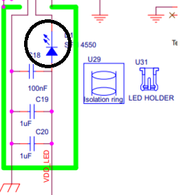
    Thank you for your fast and detailed help! I just realized that OPT3101EVM is connected with LED and photodiode and isolated with a lens.

    Can I detach the LED and photodiode in the isolated pillar in the OPT3101EVM? I want to know how LED and photodiode are connected with OPT3101EVM, and how to replace them with my VCSEL and photodiode.

    Best,

    Minseong

  • Hi Minseong,

    Sorry for the delay. I had replied here last week but seems there was a connection error and it did not go through. The LED and PD are just through hole components soldered to the PCB. The metal ring (pillar) is used for shielding and is a separate component. LED and PD can be removed. You can leave the rings if they work well for your new components. If rings are removed as well you would need to consider optical and electrical shielding. For SMT components usually only optical shielding is needed and for thru hole both electrical and optical shielding are needed. Also please keep in mind that swapping components affects the device calibration. You would need to redo calibration for best performance (see how to doc on calibration posted online).

    More details on the shielding requirement (for crosstalk) in section 8.1 in www.ti.com/.../sbau305a.pdf specifically 8.1.2 and 8.1.3.

    Best,

    ALex
  • Hello Alex,

     I appreciate your detailed information, and glad to purchase this product! In case of the swapping, can I re-calibrate the device using the software? And is there any reference swapping example or forum? Thank you.

    Best.

    Minseong

  • Hi Minseong,

    The calibration procedure is rather intensive. We provide an SDK in C++ that includes the base methods for performing calibration. The minimum re-calibrations to perform would be phase offset and crosstalk offset calibrations. I included some links below to give an idea of the process.

    Calibration guide: http://www.ti.com/lit/pdf/slau791

    SDK overview video (sdk is used to do calibration routines): https://training.ti.com/opt3101-sdk-training?cu=1136817

    Configurator tool video: https://training.ti.com/opt3101-configurator-tool-training?cu=1136817

    Best,

    Alex

  • Thank you Alex! I will try to read your link!

    Minseong