This thread has been locked.

If you have a related question, please click the "Ask a related question" button in the top right corner. The newly created question will be automatically linked to this question.

AWR1642BOOST: Access data before or after FFT processing

Part Number: AWR1642BOOST
Other Parts Discussed in Thread: AWR1642

Good day, 

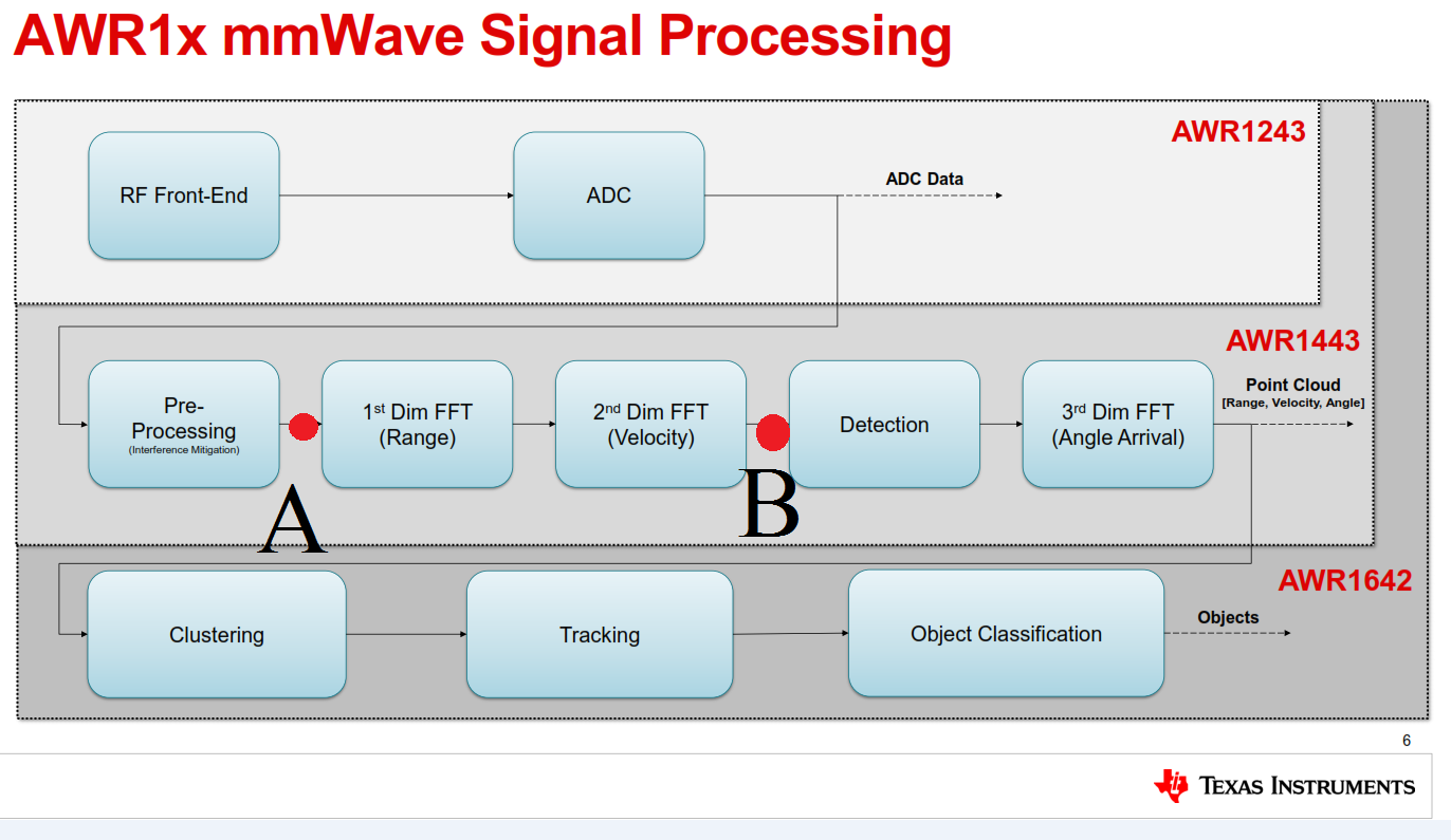
There is an application I want to do using the AWR1642 device. Its signal processing chain is shown in the diagram below.


Somewhere on this forum I saw a thread which said "You can leverage the on-board DSP for developing your algorithms" and some post said "you can also use the on-board memory - though its so small" but i forgot the links where I saw that - but I am pretty sure those two claims are possible.

What I want for my application is to get hold of the data at points A or B as shown in the diagram above, and do my processing or remove some blocks such as clustering. Which file can I use to do that?

  • Hi,

    My understanding is that you would like to modify the processing displayed in the block diagrams above.

    First, I think you should be very familiar with the mmWave SDK OOB demo. This processing blocks in the OOB demo are identical to the 2 first raws in the diagram above.

    If the changes you would like to implement are not significant, it is recommended to modify the OOB demo directly.

    If the changes you would like to implement are major, the recommended path to develop new processing algorithms is the following

    1) Capture raw data of the use case using the DCA1000 capture card.
    2) Implement the algorithm in a higher programming language such as C, matlab, python..
    3) Implement the algorithm on the AWR1xxx target.

    I hope this helps

    thank you
    Cesar
  • Hi,
    Thanks Cesar - i understand you.
    I understand the part about the additional capture card but as I was reading through the resource explorer, there are some examples which do not need the capture card - for example, the Medium Range Radar (Lab 0007).

    The diagram I have provided earlier on was simply to provide some context to what I want to do - leverage on-board dsp for processing.
  • Yes, your understanding is correct.
    ALL the demos we have available do not require the DCA1000 card since raw data is not captured on the PC. Only the processed data (also called object data) is sent to the PC through UART. The processing chain implemented on the DSP can be modified as needed.

    DCA1000 card is useful when a new processing chain has to be developed from scratch

    thank you
    Cesar
  • Yes that correct, I intend to modify the processing chain implemented on the DSP.

    Taking the Medium Range Radar lab as an example, there are a lot of .c++ and .m files in the src and gui folders and mapping the processing blocks to the C++ files is proving a bit challenging for me. I couldn't find documentation in the docs folder which explains what each file does.
  • The MRR/USRR lab processing chain uses what we call "subframes". So, it is a more advanced processing chain.

    It may be easier to start with the mmwave SDK OOB demo.

    What type of updates do you want to implement in the processing chain

    thank you
    Cesar