This thread has been locked.

If you have a related question, please click the "Ask a related question" button in the top right corner. The newly created question will be automatically linked to this question.

LMP91000: Varying TIA Gain with changes in reference bias setting

Part Number: LMP91000

Hello TI

We are developing a gas sensor board and have a need to test our board for general functionality before investing in sensor installation and test.  Primary among the functions we are testing is the TIA gain.

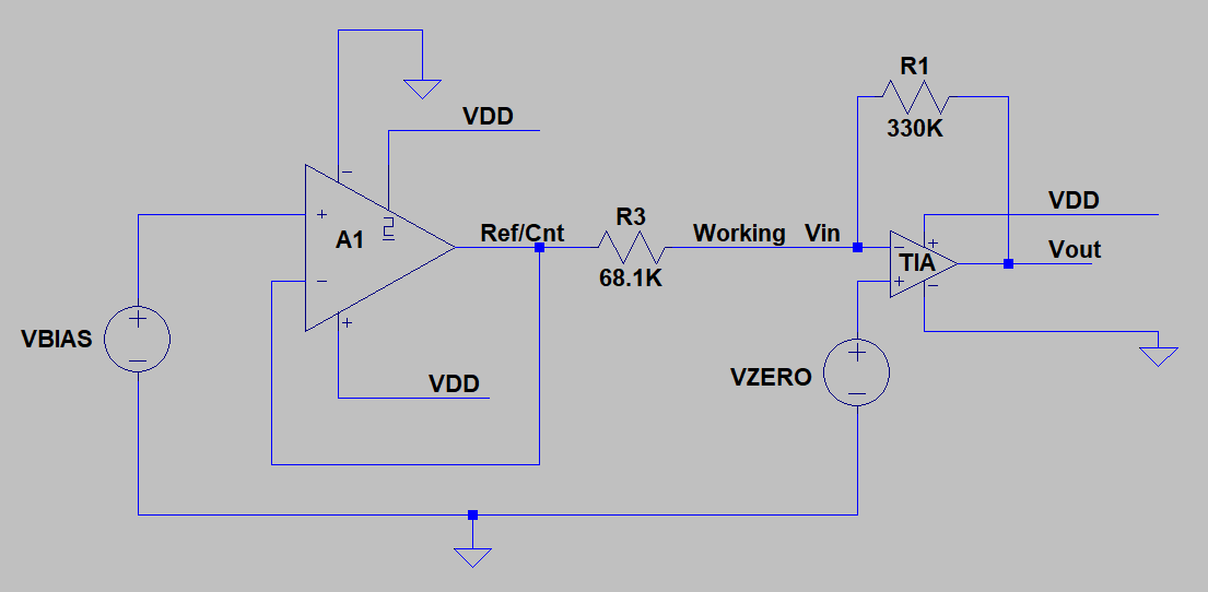
The TIA is configure with an external precision 330k resistor, using positive 20% ref internal zero setting.  We have a very simple test that involves shorting the CE and RE pins and placing a precision 68.1K resistor between them and the WE pin.  This should allow us to step through the reference bias setting from 0 to 20%, resulting in a "precision" current being injected into the WE pin, to confirm the TiA Gain.

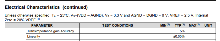
Problem: The apparent TIA gain is changing with the ref bias setting.  The value is closer to "correct" at higher bias level and more than 5% high at the lower settings.

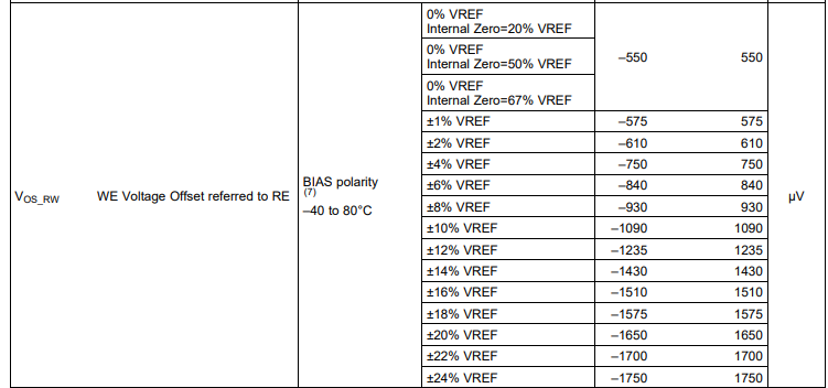
I cannot find any specs concerning the 91000 that add up to this level of TIA error.  

What can I possibly be missing?

Thank you kindly

Robin A Robinson

Principle engineer,

TANSTAAFL LABS

  • Hi Robin, 

    I will look into this and get back with you.

    Jalen

  • Hello Jalen,
    Thank you for the quick response.   Not to be pushy, but from our project perspective, time is a critical concern.  Any expedience you can offer is greatly appreciated. 
    Thank you kindly 
    Robin A Robinson 
    TANSTAAFL LABS 
    O.B.O. iDrink Inc.
    Las Vegas,  NV
    702 326 1758.


    Sent from my Samsung Edge.

    On Tue, Jun 4, 2019, 12:14 PM Jalen Tate89 <bounce-4697232@mail.e2e.ti.com> wrote:


    A Message from the TI E2E™ Community
    Texas Instruments


    Jalen Tate89 replied to LMP91000: Varying TIA Gain with changes in reference bias setting.

    Hi Robin, 

    I will look into this and get back with you.

    Jalen


    You received this notification because you subscribed to the forum.  To unsubscribe from only this thread, go here.

    Flag this post as spam/abuse.

    refid:4dcfb0f8-5431-42a4-8dbf-5013cd5ed9e3

  • Robin,

    If I am understanding correctly, you are essentially replacing the cell with a precision resistor in which you'd be able to have an expected current output. You are then measuring from the Vout pin to conclude if your TIA gain is the right value, but you are seeing too much error? Is this correct?

    Can you share a schematic/diagram of your set up? Can you also share more information on the expected values vs what you are seeing in experiment (also how you are measuring your values)?

    Additionally, can you share your register settings with me?

    Thanks,

    Jalen

  • Hello Jalen, 
    Let met get to my computer and I will forward the requested information to you.
    Thanks 
    Robin

    Sent from my Samsung Edge.

  • Hello again Jalen,
    You are basically correct, however the ref and count pins are tied together making A1 a buffer for the BIAS source.  The BIAS is then stepped through the setting mentioned above, which should result in a known (to within device specs) current being injected in to the TIA.  Below is a snippet schematic showing the basic configuration:
    image.png
    As mentioned before the registers are configured as follows"
    TIA Control =        0x00 (External Gain Resistor, 10 ohm Load)
    MODE Control =   0x03 (Sorting FET Disabled, 3 Lead Amperometric Mode)
    REF Control = 0x90 to 0x9B (External Ref, 20% IntZero, Positive Bias, Bias Level Step from 0% to 20%)
    This should result test currents steps very close to 0, 300, 600, 1200... 6,000 nA.  
    When the gain is calculated from these currents, here are the results:
    355000 Ohms @1% Bias
    351290 Ohms @2% Bias
    351290 Ohms @4% Bias
    344720 Ohms @5% Bias
    342672 Ohms @8% Bias 
    341038 Ohms @10% Bias
    339956 Ohms @12% Bias
    339088 Ohms @14% Bias
    338599 Ohms @16% Bias
    338156 Ohms @18% Bias

    I am sure there must be a reasonable explanation for this and a correction, but I can see through it without more info on the 91000.

    Thank you again,
    Looking forward to your response,
    Robin A. Robinson


  • The graphics rendering does not show the connection between amplifier A1 inverting input and output.  It is there in the email, but not on the post.

  • Hello again Jalen, 
    Any progress on this?
    Thanks
    Robin

    Sent from my Samsung Edge.

    On Wed, Jun 5, 2019, 8:41 AM Robin Robinson <robin@tanstaafl-labs.com> wrote:
    Hello again Jalen,
    You are basically correct, however the ref and count pins are tied together making A1 a buffer for the BIAS source.  The BIAS is then stepped through the setting mentioned above, which should result in a known (to within device specs) current being injected in to the TIA.  Below is a snippet schematic showing the basic configuration:
    image.png
    As mentioned before the registers are configured as follows"
    TIA Control =        0x00 (External Gain Resistor, 10 ohm Load)
    MODE Control =   0x03 (Sorting FET Disabled, 3 Lead Amperometric Mode)
    REF Control = 0x90 to 0x9B (External Ref, 20% IntZero, Positive Bias, Bias Level Step from 0% to 20%)
    This should result test currents steps very close to 0, 300, 600, 1200... 6,000 nA.  
    When the gain is calculated from these currents, here are the results:
    355000 Ohms @1% Bias
    351290 Ohms @2% Bias
    351290 Ohms @4% Bias
    344720 Ohms @5% Bias
    342672 Ohms @8% Bias 
    341038 Ohms @10% Bias
    339956 Ohms @12% Bias
    339088 Ohms @14% Bias
    338599 Ohms @16% Bias
    338156 Ohms @18% Bias

    I am sure there must be a reasonable explanation for this and a correction, but I can see through it without more info on the 91000.

    Thank you again,
    Looking forward to your response,
    Robin A. Robinson


  • Hey Robin,

    As far as datasheet specs the only reference I see to your measurement is that there is a 5% transimpedance gain accuracy and a voltage offset that varies depending on the bias voltage.

    Jalen

  • Jalen,
    I would hope the gain number would be for the internal resistors,  not the external.  Any chance you can confirm my measurements on one of you own eval boards.  And more importantly, why would the gain change with the bias setting?

    We have a requirement to calibrate out as much of the errors as possible.  But I have no idea where these error are coming from.  

    I am looking for a recommendation on how to use this information to reduce errors.  

    Any help would be appreciated.

    Thank you kindly. 
    Robin

    Sent from my Samsung Edge.

  • Robin,

    You are correct, the gain number is for the internal resistor. I misspoke, there is a min & max offset depending on the step of your bias voltage which is what the datasheet spec shows.

    Can you provide the Vref you are using as well as the output voltages you measure at the Vout pin? 

    Have you measured all of the expected values (i.e precision resistors, current through R3) and used the measured values in calculations to be sure?

    I believe you could be seeing the sum of different errors such as any variation in the biasing levels along with the offset errors of the amplifier itself.

    Jalen

  • Hello again Jalen,

    I have measured the "external" factors of the precision resistor and the reference voltage on our board.  What I have not done, but don;t believe it to be an issue is "characterized"  the amplifier and ADC that are between the 91K and process.  These are well qualified parts in this regime and I have never seen them cause this level of error in any other circuit.  The hopes was to use the tightly speced  (< .+/-0.5% worst case ) bias as the source for injecting a current into the TIA and characterize the gain across all usable settings. When I worse case all "documented" errors, it is less that 1%.   The board circuit actually measures the difference between the Vout and (buffered) C1 pins, so I am, in effect measure the voltage across the gain resistor.  I would be much less concerned. if the error were more constant across the bias settings, but it is not, so now the quandy, how to use this data to "calibrate" the board gain, and more problematic, is this error due to bias errors, or due to actual gain errors?  At the very least, I would appreciate you guidance on how to use this data.  At the very most, I would hope you could offer repeat similar testing there with your resources and report you findings and how to use the data.

    This intent here was fold all the board errors of 91k and the remaining board components into one simple measurement taken at several bias settings.  Had the results been more in line with the worst case specs, I would have moved on.  When I add up all the worst case errors I am well under 1% which is more than acceptable.  But at these error levels, I am unsure how to handle the matter appropriately. Let me know if you want to see the board circuit, so you can replicate my worst case calcs and help prove me wrong (or right).  

    Thanks again,

    Robin

    PS, is there any way to post a graphic image from within this web page without using email?  I can figure it out if there is.

  • Robin - 

    I work with Jalen and saw this post - have you tried your experiment with a 1M Ohm resistor in between RE/CE (shorted) and WE instead of a 68.1k? 

    I found where at least one other user had done this with success - have not dug into if more current might do what you are seeing yet - but - saw this and thought to share it. 

    Please see ==> https://www.zimmerpeacocktech.com/knowledge-base/faq/lmp91000-trouble-shooting/, test 3

  • Hello Josh, Jalen,
    The reason for 68.1k, as you probably recognize, is to reach max simulated sensor current (600 nA) at the max "usable" bias setting (+ 20%).  I see nothing in the 91000 specs that would indicate a problem delivering current at this level.  Am I missing something?  

    I have not tried any other resistance values, but, if you can give me a valid reason that 68.1 k won't work, I certainly will try.

    FYI, although the error is large (from my perspective) it is repeatable, ie does drift over nominal conditions.

    My biggest concern here, which I previously stated, is where this error come from.  Ie, is it a TIA gain issue, or a bias source issue.  Knowing this, I could properly compensate.

    But at this juncture I only know there is an error outside the device specifications.  

    Looking forward to hearing from you with a reasonable path forward. 

    Thank you kindly
    Robin Robinson 


    Sent from my Samsung Edge.

  • Hello Jalen, Josh,
    Any further progress on this?
    Thanks
    Robin

  • Robin - 

    Yes - we ordered a sensor to check whole system - looks like it came in, so we should be able to get into this shortly - it's a short week here, but we will try to get to it with some priority. 

    sorry for the delay

  • Hi Josh,
    Thanks for the update.  However, the problem I am having is before we mount the sensor.  It is with a precision resistor.  Is that what you mean?
    Thanks
    Robin

    Sent from my Samsung Edge.

  • Hi Robin,

    What is the reference voltage you are using?

    Can you try adjusting the internal zero to 67% of the reference and see if this helps with the error you see at the different bias levels?

    Jalen

  • Hi Jalen,
    We are using a 2.048 Volt reference.

    Sent from my Samsung Edge.

  • Robin,

    Can you try adjusting the internal zero to 67% of the reference and see if this helps with the error you see at the different bias levels?

    Jalen

  • Hello Jalen,
    I will try this, but flies in the face of the sensor mfg settings recommendations.   What do you think might be the issue at the lower level?
    Robin


    Sent from my Samsung Edge.

  • Robin,

    I believe there could be two sources of the error you see.

    1) There is a resistor ladder internally that is not trimmed, so I believe that could be contributing the increased error you see as you lower bias steps.

    2) I also believe that you are driving the TIA negative rail too close to GND. If you increase the Internal Zero, you'd allow for my headroom here. 

    For these reasons, I;d like to see if adjusting the internal zero gives you a little more linearity.

    Jalen

  • Hello again Jalen,
    And thank you again for the continued support.  I have not yet tried the elevated internal zero setting as I am "on vacation" with my grandchildren.  I will indeed try it, likely next week, however, I am as concerned with the separation from the specifications as I am anything.  Can you point me towards anything in the specs that would indicate this is an acceptable error condition?  Also, have you tried this on your own board, and if so, what were your findings?
    Thank you,
    Robin

    On Mon, Jul 15, 2019, 12:07 PM Jalen Tate89 <bounce-4697232@mail.e2e.ti.com> wrote:


    A Message from the TI E2E™ Community
    Texas Instruments


    Jalen Tate89 replied to LMP91000: Varying TIA Gain with changes in reference bias setting.

    Robin,

    I believe there could be two sources of the error you see.

    1) There is a resistor ladder internally that is not trimmed, so I believe that could be contributing the increased error you see as you lower bias steps.

    2) I also believe that you are driving the TIA negative rail too close to GND. If you increase the Internal Zero, you'd allow for my headroom here. 

    For these reasons, I;d like to see if adjusting the internal zero gives you a little more linearity.

    Jalen


    You received this notification because you subscribed to the forum.  To unsubscribe from only this thread, go here.

    Flag this post as spam/abuse.

    refid:4bce07a1-9841-4905-8749-52913dd10140

  • Hello Again Jalen,
    I have aquired the "board cal" data at both alternate internal zero settings (67% and 50%).  I have yet t fully analyze it, but with both settings the top gets clamped before the tia reaches full output.  The TIA output at our default zero setting (20%) seem to be reasonable, and in fact at that level the gain calc is the closest at the upper bias settings, so I dont believe it to be a TIA issue.  Is there a spec that suggests some reduced range of acceptable bias settings?

    I will calc the effective TIA gain and get back to you sometime later this week.
    Thanks again,
    Robin

  • Robin,

    Do you have any update to the effective TIA gain at the alternate internal zero settings?

    As far as the specs you are concerned about, the TIA gain accuracy is 5%, but this is a typical spec. There is no min or max limit mentioned in the EC table, so it could be possible that your configurations would result in higher error.

    Jalen

  • Hello Jalen,
    I have briefly looked at data from several boards now and the findings are essentially the same regardless the internal zero setting.  The only big change is that the bias appears to saturate at the 50% and 67% levels, even though there should be sufficient headroom (Delta bias = 20%).  That is the gist of my last question.  Is there some upper limit to the bias setting relative to VDD?  Nothing I see in the spec sheet would suggest this.
    Thanks
    Robin

  • Hello Jalen, Josh,
    Just a note to let you know that I am now forced to abandon any hope of using the 91000 reference/bias settings to help "calibrate" our boards.  It would have been an ideal situation had it worked out.  So you may now close this case if you like.  

    However, I must say I am ultimately disappointed in my findings for this part, particularly w/r/t how it is specified, and have every intention of designing it out of our next board revision.  Please don't take this personally, as I am sure you have tried to help to limits you are allowed and/or capable.  I am just finding far too many "exceptions" to the specifications as published, and not receiving any confirmation or alternatives.
    Thank kindly for the time you may have invested in this.

    Robin

  • Thank you Robin I will move forward with closing this post.

    Jalen

  • Hi Jalen,
    I really do wish we could have come to resolution on this issue.  I am a staunch TI advocate, but this chip is either not performing within the published specifications, or the specifications are wrong, in my humble engineering opinion.  If you ever have the opportunity to look at this with hardware at your end, I would appreciate the effort and will reconsider if a path can be made for using the bias steps as a "precision" source for testing.  I think this would be a truly beneficial to the product and it's market place.
    Thank you again for your efforts
    Robin @ TL
    Robin