This thread has been locked.

If you have a related question, please click the "Ask a related question" button in the top right corner. The newly created question will be automatically linked to this question.

IWR1642: No crystal oscillations. Custom PCB help!

Part Number: IWR1642
Other Parts Discussed in Thread: AWR1642,

No generation on crystal oscillations.

Chip:

IWR1642

QG

82ZE3Y9

502AC ABL G1


Crystal: CX3225SA40000D0PTWCC

The basis was taken project Altium IWR1642BOOST RevB EVM design package (proc11B_iwr1642altium.zip). From it, the interfaces we no longer need were carefully removed. The power system remained the same. The power architecture remained untouched. All converters, their trace, location, remained the same. The resulting project was tested and made in accordance with the requirements of "HardwareDesignChecklist_V0p7_AWR1642_SWRR154.xlsx". TMS, TCK, TDI pins are not connected (they have a Pull Up/Down inside the IWR1642 chip). The measured power supply value and the noise level are the limits. Measured the power supply value is the same as on the IWR1642BOOST debug board (we have it, I compared it with its values).

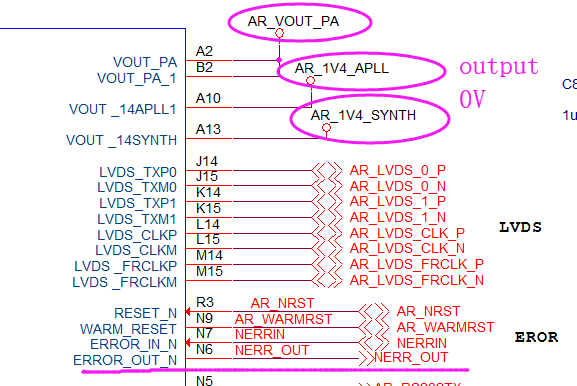
When powering the board, after 264 ms, the pin ERROR_OUT (pin N6 of the IWR1642 chip) is transferred from log.1 to log.0. This indicates that there is a hardware error. After WARM_RESET come from level 0 to level 1, voltage on VBGAP (pin B10 of IWR1642 chip) begins to appear and has a rms level of 893 mV, but the power on this pin grows exponentially and the time to establish the order of 500 ms. At the VOUT_14APLL and VOUT_14SYNTH pins, the supply voltage is 34-37 mV (i.e. it is absent). At the CLKP pin (pin C15 of the IWR1642 chip), the voltage is 32mV DC at the CLKM pin (pin D15 of the IWR1642 chip), the voltage is 437mV DC. Voltage on CLKM  and CLKP pins are grows exponentially and the time to establish the order of 500 ms  There is no generation. After the power was established and ERROR_OUT triggered, I apply log.0 to RESET pin IWR1642, but ERROR_OUT again indicates hardware error.

     We can not established connection to the UART terminal with the chip. At the same time, there is a connection via the UART terminal with the IWR1642BOOST debug board.

I thought the chips was badly soldered. I gave it to warm up. After warming up, nothing has changed.

We soldered three boards and all behave the same.

Is my chips burned out (all three board assembly and soldered together)?

Or design errors?

And in the absence of generation on a crystal, should there be a UART terminal connection with the chip?

My IWR1642 scheme:

  • Hi User,

    We will need some time to look into this so please allow a few days for a response.

    Cheers,

    Akash

  • Hello,

    Did you check for any shorts before assembling the PCB?

    Are you seeing the correct voltages on the PMIC outputs and at the AWR supply decoupling caps?

    Are you ensuring that the NRST pin is asserted >3ms after all of the supplies have reached steady state?

    Regards,

    Adrian

  • Hello ,
       I have meet  the same promblem  almostly ,
    After the power was established and ERROR_OUT triggered( ERROR_OUT  Pin N6 get to 0V);
      I  check My PCB, there is no any shorts, and the Power consumption is 5V , 0.25A;
      I check the clock by the oscilloscope , which is 40MHz ;
      The Reset is OK,too
      The voltages on the  IWR1642  , such as 3.3V , 1.8V , 1.2V , RF 1.3V ,are correct;
    but I find the voltages  VOUT_14APLL = 0V,  and  VOUT_14SYNTH =0V, VOUT_PA = 0V,   are   wrong ;
         and the ERROR_OUT triggered
         

  • Hi,

    Have you made any progress with this?

    Can you share the full schematic? if all the boards are failing its more likely that there is a fault in the design. 

    Regards,

    Charles O

  • Hi, Charles O,

        I have solved the problem;

       The SOP0 and SOP1  are charged  10ms From another  MCU  IO   when powered-on;

       thanks!

  • Hello, Charles Oladimeji.

    How IWR1642AQAGABL sensivity to power supply noise level?  

    Next week, I'll be back to working on the radar. There are suspicions that I did not correctly determine the level of noise of power supplies.
    What is the most sensitive supply to the radar?
    At the output of the VBGAP (pin B10 of IWR1642 chip) rms level of 893 mV, but the supply on this pin grows exponentially and the time to establish the order of 500 ms.

    I can an share the full schematic, but confidentialy. Where to send it?

  • Hi,

    The RF and High speed pins are usually the most susceptible. Can you compare with the EVM to see if this is expected behaviour? 

    Regards,

    Charles O

  • Charles Oladimeji said:

    Hi,

    The RF and High speed pins are usually the most susceptible. Can you compare with the EVM to see if this is expected behaviour? 

    Regards,

    Charles O

    I compared the power supply value EVM with my board. Measured the power supply value is the same as on the IWR1642BOOST debug board. The measured power supply value and the noise level are the limits.
    But there is a big difference: in the EVM board, the VBGAP voltage is established quickly, almost abruptly. The voltage VBGAP on my board is set slowly, exponentially, about 200 ms. It looks like the capacity is slowly charging.

    "It looks like the capacity is slowly charging." - 

    This thought put me on the right path! It turned out that the capacitance was sealed not by 0.22 μF, but by 2.2 μF at the VBGAP pin.
    Replaced the nominal capacity of 0.22 μF and it all worked !!! Thanks to all!