This thread has been locked.

If you have a related question, please click the "Ask a related question" button in the top right corner. The newly created question will be automatically linked to this question.

IWR6843: Chirp configuration for running one single Tx on IWR6843 fails

Part Number: IWR6843

I am trying to run the  IWR6843 using only Tx1.

Using mmwave_sdk_03_00_00_08

When configuring the IWR6843 I get the config echoed back on the UART as expected but it ends with:

mmwDemo:/>Poll messages*

sensorStart

Debug: Init Calibration Status = 0x1e

Exception: ./mss/main.c, line 1197.

Error: mmWave Config failed [Error code: -3108 Subsystem: 46]

xdc.runtime.Main: "./mss/main.c", line 1197: assertion failure

xdc.runtime.Error.raise: terminating execution

I was expecting this:

mmwDemo:/>Poll messages*
sensorStart
Debug: Init Calibration Status = 0x1e
App: Issuing DPM_start
Starting Sensor (issuing MMWave_start)
Done
mmwDemo:/>Config done

The config file I am using is seen below. I have a firmware running that is working fine with other config files using Tx1 + Tx3, using the last config file below.

I must have made some mistake when moving to using only Tx1, but I can not spot it. Are there any examples of configurations using only one Tx?

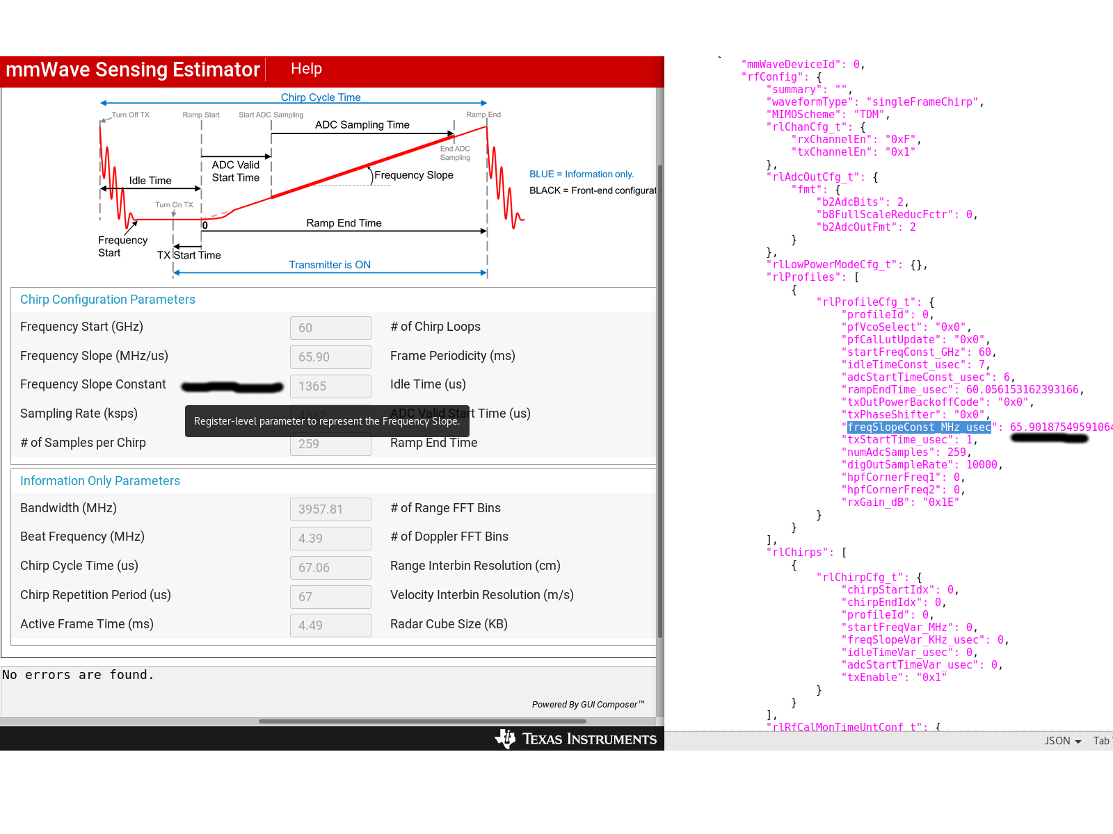
My goal is to chirp over a bandwidth of 4000GHz (as much of it as possible) using Tx1 (first Tx).

I have used mmWave Sensing Estimator https://dev.ti.com/gallery/view/1792614/mmWaveSensingEstimator/ver/1.3.0/

to get the current single Tx configuration file.

Grateful for any input.

--------------------------Single Tx config file, not working.----------------------------

sensorStop
flushCfg
dfeDataOutputMode 1
channelCfg 15 1 0
adcCfg 2 1
adcbufCfg -1 0 1 1 1
lowPower 0 0
profileCfg 0 60 7 6.00 60.06 0 0 1365 1 259 4882 0 0 36
chirpCfg 0 0 0 0 0 0 0 1
% chirpCfg 1 1 0 0 0 0 0 4 - Removed since we are not using Tx 2
frameCfg 0 0 128 0 100 1 0
guiMonitor -1 1 1 1 0 0 1
cfarCfg -1 0 2 8 4 3 0 1200 0
cfarCfg -1 1 0 4 2 3 1 1200 0
multiObjBeamForming -1 1 0.5
calibDcRangeSig -1 0 -5 8 256
clutterRemoval -1 0
compRangeBiasAndRxChanPhase 0.0 1 0 1 0 1 0 1 0 1 0 1 0 1 0 1 0 1 0 1 0 1 0 1 0
measureRangeBiasAndRxChanPhase 0 1. 0.2
aoaFovCfg -1 -90 90 -90 90
cfarFovCfg -1 0 0 45
cfarFovCfg -1 1 -10 10
sensorStart

--------------------------Double Tx config file, working.----------------------------

sensorStop
flushCfg
dfeDataOutputMode 1
channelCfg 15 5 0
adcCfg 2 1
adcbufCfg -1 0 1 1 1
lowPower 0 0
profileCfg 0 61 23.656 7 74 0 0 6.662 1 128 2000 0 0 36
chirpCfg 0 0 0 0 0 0 0 1
chirpCfg 1 1 0 0 0 0 0 4
frameCfg 0 1 128 0 100 1 0
guiMonitor -1 1 1 1 0 0 1
cfarCfg -1 0 2 8 4 3 0 1200 0
cfarCfg -1 1 0 4 2 3 1 1200 0
multiObjBeamForming -1 1 0.5
calibDcRangeSig -1 0 -5 8 256
clutterRemoval -1 0
compRangeBiasAndRxChanPhase 0.0 1 0 1 0 1 0 1 0 1 0 1 0 1 0 1 0 1 0 1 0 1 0 1 0
measureRangeBiasAndRxChanPhase 0 1. 0.2
aoaFovCfg -1 -90 90 -90 90
cfarFovCfg -1 0 0 45
cfarFovCfg -1 1 -10 10
sensorStart

  • Correction:

    It looks like the mmWave Sensing Estimator tool showed some values in the GUI but when exporting the file, other values were shown.

    I will test these other values.

    -------------------------------Chirp config that was accepted------------------

    sensorStop
    flushCfg
    dfeDataOutputMode 1
    channelCfg 15 1 0
    adcCfg 2 1
    adcbufCfg -1 0 1 1 1
    lowPower 0 0
    profileCfg 0 60 7 6.00 60.0561 0 0 65.9019 1 259 10000 0 0 36    
    chirpCfg 0 0 0 0 0 0 0 1
    frameCfg 0 0 128 0 100 1 0
    guiMonitor -1 1 1 1 0 0 1
    cfarCfg -1 0 2 8 4 3 0 1200 0
    cfarCfg -1 1 0 4 2 3 1 1200 0
    multiObjBeamForming -1 1 0.5
    calibDcRangeSig -1 0 -5 8 256
    clutterRemoval -1 0
    compRangeBiasAndRxChanPhase 0.0 1 0 1 0 1 0 1 0 1 0 1 0 1 0 1 0 1 0 1 0 1 0 1 0
    measureRangeBiasAndRxChanPhase 0 1. 0.2
    aoaFovCfg -1 -90 90 -90 90
    cfarFovCfg -1 0 0 45
    cfarFovCfg -1 1 -10 10
    sensorStart

  • Configuring now gives a

    ..

    mmwDemo:/>Poll messages*
    sensorStart
    Debug: Init Calibration Status = 0x1e
    Error: DPM Report 4 received with error:-40111 arg0:0x64 arg1:0x8003fd8
    xdc.runtime.Main: "./mss/main.c", line 1746: assertion failure
    xdc.runtime.Error.raise: terminating execution
    Config done

    Where can I find the documentation about DPM Report error codes?

    DPM Report 4 received with error:-40111 arg0:0x64 arg1:0x8003fd8

  • Former Member
    0 Former Member in reply to Johanwww

    The IWR6843 device only supports up to 8Ghz chirp bandwidth. Looking at the 1TX chirp configuration you provided it looks like you are trying a profile that spans greater than 8GHz.

    This is not supported and will give an error.

    Amanda

  • Hi

    Thanks for your input.

    Looking at the IWR6843 info page, it looks to me like the IWR6843 only suppors 4GHz continuous bandwidth in the range 60-64GHz, I never intended to exceed that, but to cover as much as possible of it. I fail to see how  my configuration exceeds this, see my calculation below.

    When I check my configurations I get my bandwidth that I try to use to 3957.69699 MHz starting at 60GHz (rampEndTime * freqSlopeConst, 60.0561×65.90MHz/us = 3957.69699 MHz bandwidth), keeping me in the range [ 60 - 63,95769699GHz ]

    But I might lack some understanding, I will double check my configuration.

  • Problem solved.

    As I can understand it I had some problems with the ADC sample rate and number of ADC samples.

    I still use about the same bandwidth according to me: (rampEndTime * slopeConstant = 74 * 53.3 = 3944.2MHz bandwidth).

    This configuration works (I can see data output on UART) but is uses two Tx, Tx1 and Tx3.

    sensorStop
    flushCfg
    dfeDataOutputMode 1

    %
    %                        - Antenna enable mask ---------------------------------------------Replace with '1' to remove Tx3
    %                        |
    channelCfg 15 5 0
    adcCfg 2 1
    adcbufCfg -1 0 1 1 1
    lowPower 0 0
    %
    %                     -startFreq
    %                    |      -idleTime
    %                    |      |     -adcStartTime
    %                    |      |     |    -rampEndTime
    %                    |      |     |    |             -freqSlopeConst [MHz/us]
    %                    |      |     |    |             |     -txStartTime  (not given by TI tool)
    %                    |      |     |    |             |     |     -numAdcSamples per chip
    %                    |      |     |    |             |     |     |        -digOutSampleRate [Ksps]
    %                    |      |     |    |             |     |     |        |
    profileCfg 0 60 23.6 7 74 0 0 53.3 1 128 2000 0 0 36
    %
    %                      -tx antenna enable mask
    %                      |
    chirpCfg 0 0 0 0 0 0 0 1
    %------------------------------------------------------------------------------------------------Tx3 - to be removed
    %                 -tx antenna enable mask
    %                 |
    chirpCfg 1 1 0 0 0 0 0 4
    %
    %                  - Number of chirp configs -----------------------------------------------Replace with '0' to remove Tx3
    %                  |
    frameCfg 0 1 128 0 100 1 0
    guiMonitor -1 1 1 1 0 0 1
    cfarCfg -1 0 2 8 4 3 0 1200 0
    cfarCfg -1 1 0 4 2 3 1 1200 0
    multiObjBeamForming -1 1 0.5
    calibDcRangeSig -1 0 -5 8 256
    clutterRemoval -1 0
    compRangeBiasAndRxChanPhase 0.0 1 0 1 0 1 0 1 0 1 0 1 0 1 0 1 0 1 0 1 0 1 0 1 0
    measureRangeBiasAndRxChanPhase 0 1. 0.2
    aoaFovCfg -1 -90 90 -90 90
    cfarFovCfg -1 0 0 45
    cfarFovCfg -1 1 -10 10
    sensorStart

    Disabling Tx1 now leaves me with a working config, see below.


    sensorStop
    flushCfg
    dfeDataOutputMode 1
    channelCfg 15 1 0 ---------------------------------------------------------------------------Tx3 Removed
    adcCfg 2 1
    adcbufCfg -1 0 1 1 1
    lowPower 0 0
    %
    %                    -startFreq
    %                    |      -idleTime
    %                    |      |      -adcStartTime
    %                    |      |      |   -rampEndTime
    %                    |      |      |   |            -freqSlopeConst [MHz/us]
    %                    |      |      |   |            |      -txStartTime  (not given by TI tool)
    %                    |      |      |   |            |      |    -numAdcSamples per chip
    %                    |      |      |   |            |      |    |        -digOutSampleRate [Ksps]
    %                    |      |      |   |            |      |    |        |
    profileCfg 0 60 23.6 7 74 0 0 53.3 1 128 2000 0 0 36
    %
    %                                    -tx antenna enable mask
    %                                    |
    chirpCfg 0 0 0 0 0 0 0 1
    %%------------------------------------------------------------------------------------------------Tx3 - Removed
    %%                                     -tx antenna enable mask
    %%                                     |
    %chirpCfg 1 1 0 0 0 0 0 4
    %
    %                  - Number of chirp configs---------------------------------------------------Tx3 Removed
    %                  |
    frameCfg 0 0 128 0 100 1 0
    guiMonitor -1 1 1 1 0 0 1
    cfarCfg -1 0 2 8 4 3 0 1200 0
    cfarCfg -1 1 0 4 2 3 1 1200 0
    multiObjBeamForming -1 1 0.5
    calibDcRangeSig -1 0 -5 8 256
    clutterRemoval -1 0
    compRangeBiasAndRxChanPhase 0.0 1 0 1 0 1 0 1 0 1 0 1 0 1 0 1 0 1 0 1 0 1 0 1 0
    measureRangeBiasAndRxChanPhase 0 1. 0.2
    aoaFovCfg -1 -90 90 -90 90
    cfarFovCfg -1 0 0 45
    cfarFovCfg -1 1 -10 10
    sensorStart

  • Former Member
    0 Former Member in reply to Johanwww

    Your bandwidth calculation is correct. I was referring to the first chirp configuration where your slope was 1395 - I now see that you updated it to a lower slope constant which is within the bandwidth.

    I will report back the bug you found in the sensing estimator where the GUI is different from the exported file.

    Best,

    Amanda

  • Former Member
    0 Former Member in reply to Former Member

    Can you also clarify why you are not using the MmWave demo visualizer to generate the 1TX configuration file you want? You could set it to max range resolution and easily generate a 1TX cfg that is guaranteed to work with the SDK demo processing chain.

  • When we started the project the Linux GUI Composer and MmWave Demo Visualizer did not supporting 60GHz for uploading configuration files to the chip, if I remember correctly, which could be solved with some changes in the softwares code. But we moved away from the tool and forgot about it. Could prove to be very useful, thanks.