This thread has been locked.

If you have a related question, please click the "Ask a related question" button in the top right corner. The newly created question will be automatically linked to this question.

PGA460: Same ultrasonic readings with or without objects present

Part Number: PGA460
Other Parts Discussed in Thread: ENERGIA

Hi, 

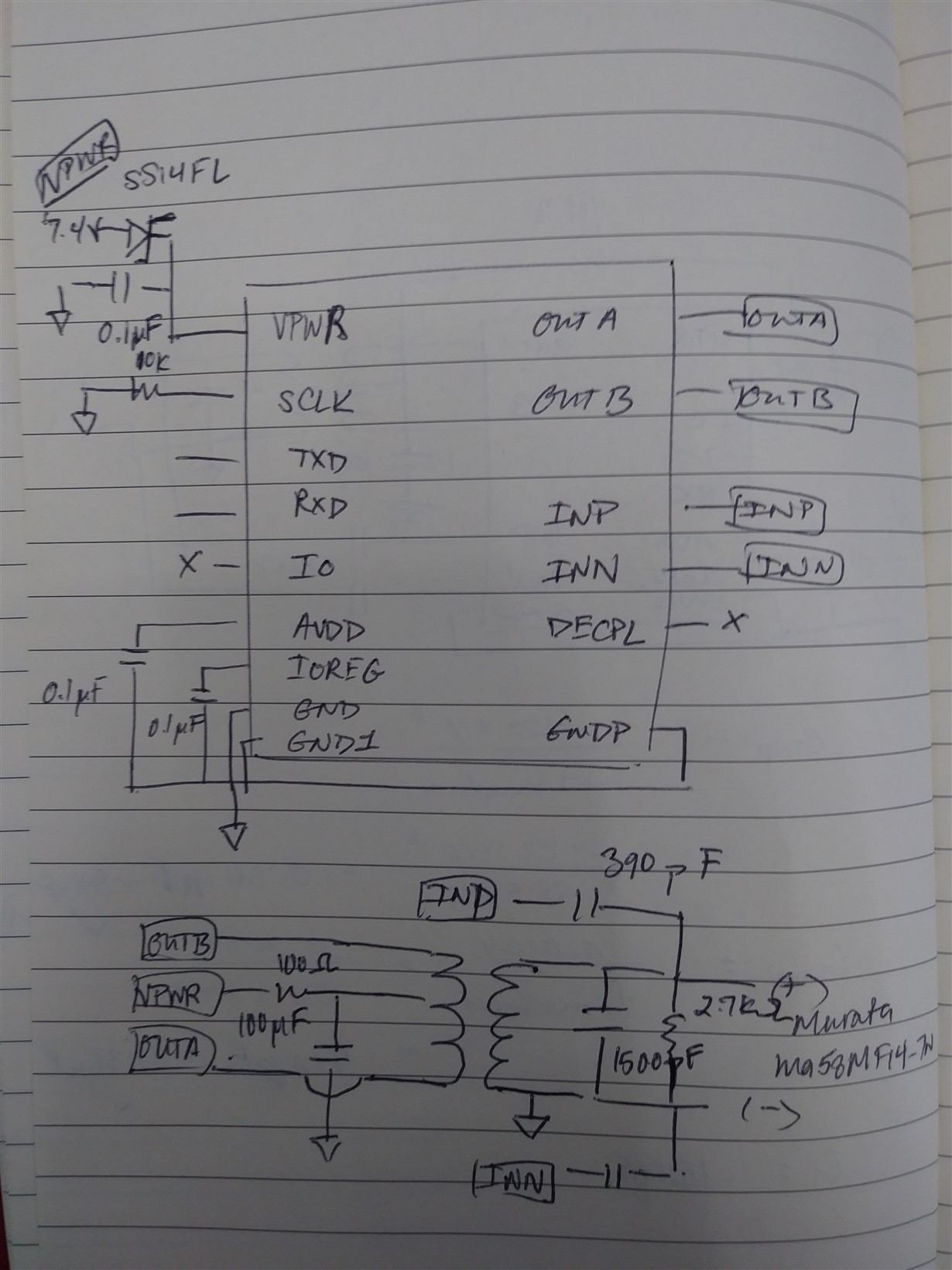
I've created a board around PGA460 to interface with Murata MA58MF14-7N and Arduino Mega 2560, and I'm having problems getting readings for object detection.

The design is based on the suggested layout from the PGA460 datasheet.

I'm using the Energia Code and Library to run the GetDistance program, with slight modification of #include <Energia.h. --> #include <Arduino.h>. Otherwise, everything is kept the same.

I have been running the code with 19.2k baudrate, set up with 8 bits, no parity, 2 stop bits.

The problem I'm running into is  that the same distance measurement keeps on appearing regardless of whether or not an object is in front of it or not. I have looked up this problem in the E2E forum and found someone experiencing the same problem (https://e2e.ti.com/support/sensors/f/1023/t/705837?PGA460-Custom-Drive-Board-Design-Issues). Below is my own record of the problem:

It was suggested from the forum that:

"For instance, the repeated result value of 2.7m from one of your examples may actually be a combination of the diagnostic field and the time-of-flight's MSB byte, rather than the time-of-flight's MSB and LSB byte. More specifically, if the diagnostic field is 0x40 and the ToF's MSB is 0x00, the the ToF according to the master is 0x4000 (16384us), which is identical to ~2.810m. You would likely see this value change if a long range ToF were captured."  - Akeem

I have tried to verify this by printing out all the elements in ultraMeasResult[] array, but found no changes in any elements when posing an object in front of the Murata sensor.

Also, it was suggested that I should try to read the values of UART transmit and receive activity: 

"I recommend that you first use a logic analyzer to check the values of the UART transmit and receive activity of the PGA460, and to ensure the diagnostic field is not a value other than 0x40. (A diagnostic field of 0x40 implies there is no UART communication error.)
Then, you should check how the actual byte values are being queued into the resulting array (in your PGA460_USSC.cpp file equivalent) of your ported code."  -Akeem

I'm not sure how to do this. I will appreciate if there's detailed instructions and code for how to do this.

Other oddities that I have observed:

1. When I unplugged the Murata sensor, the measurement keeps on displaying the same number instead of outputting like "No data".

2. I've tried probing with an oscilloscope at INP and INN, and the signals are constant. I have tried exciting the INP with a small voltage, hoping to see a change in measurement but nothing changed.

3. RX pin on PGA460 is pulled highed for some reason.

4. Switching on and off the power supply will sometimes give a different measurement number.

Thanks in advance for any help

Uyen

  • Hi Uyen,

    Thank you for your detailed question. I will be able to reply in greater detail on Tuesday, but will suggest the following in the meanwhile:

    1) Does changing the threshold level result in a different distance value (you are currently using midcode)? If so, you will need to either generate a custom threshold case, or reduce the digital gain multiplier value hardcoded in the bulk EEPROM write configuration.

    2) Does a listen only command result in the same value?

    3) Can you implement an example sketch whereby you echo back a single register's data? This will require use of the registerWrite and registerRead functions in the PGA460_USSC.CPP file, and help verify if the data you are writing to a single register is reported back properly.

  • HI Akeem,

    Thank you for replying so quickly!

    1. I have tried all different combinations of threshold values(levels) in combination with different AFEGAIN ranges and TVG values(%). I have tried all of these steps on two other custom pcbs, and the same problem still occurs. I have yet to generate a custom threshold case; do you have a suggestion for doing this in an efficient way.

    2. I have also tried Listen Only command, and there's still no changes.

    3. I will try the registerRead and registerWrite command after initPGA460  in setup. What am I expecting to see for a proper transmission?

  • Hello Akeem,

    So I tried registerRead(0x2B) I got back {0 63 63} as the response which I know is incorrect (I assume that I should be expecting {40, some value, CB}).

    What do you suggest could cause this problem, and what can I do to fix it?

    Thanks,

    Uyen

  • Hi Uyen,

    You should confirm that the device is actually responding with 0x{00 63 63} by using an oscilloscope or digital logic analyzer. Can you capture this UART TXD register read response waveform? I have never seen these values in a response (the first byte should always have bit 6 = 1, i.e. 0x40), so I suspect the UART configuration is erroneous, or the serial buffer has not been properly cleared prior to the command. This may be Serial issue specific to the Arduino, which I do not have any experience with.

  • Hello Akeem,

    The numbers appeared to be in hexadecimal form. One suspicion I have for the 0x00 as the diagnostic byte is that I executed registerRead() right after initPGA460() in the setup() - I'm uncertain about this theory, maybe you can confirm this for me. One progress on my part is that I managed to fix the diagnostic byte for every ultrasonic measurement to be 0x40 after putting a pull-up resistor on the PGA460 TXD. After this fix, even though the first byte is still 0x00 for registerRead() in the setup, I was able to get the correct value at the register address.vHowever, the constant erroneous distance measurement of 5.98m did not go away. One more observation that I have made is the EEPROM burn is only successful whenever the power supply is off for me. Is this supposed to happen?

    Thanks,

    Uyen

  • Hi Uyen,

    Can you provide the actual PGA460 UART output as captured via a digital logic analyzer or oscilloscope? I am trying to replicate your error. The closest I've been able to get attempting to read the ultrasonic measurement result prior to the THR_CRC_ERR being cleared. When executing command 5 under these conditions, the values returned are 0x{ 40, BF, 00, 00, 00}, which is decoded as diagnostic byte (0x40) = no error, ToF in microseconds (0xBF00), width (0x00), and peak (0x00). This indicates that no object was detected; however, if you assume the ToF to be 0xBF00 = 48.9ms, this equates to 8.38m.

    Can you perform a register read to check if the THR_CRC_ERR is cleared (bit =0) from the DEV_STAT0 register before attempting to burst/listen. It is possible that the threshold is not getting written to in order to clear this bit after start-up, and thereby reporting a constant value as a result (in your case, 5.98m). You can also check the width and amplitude bytes. If they are non zero, the object being reported is a real threshold crossing, and the settings must be optimized. However, if they are both zero, then the UMR is not being updated due to a lack of the THR_CRC_ERR being cleared, or the device not executing a burst/listen command to update the UMR afterwards. You can probe the transducer’s positive terminal using an oscilloscope to ensure the device is actually bursting.

  • Hello Akeem,

    You are absolutely genius! THR_CRC_ERR bit was not cleared and that's what caused the constant value of 5.98m. The first time that we registerRead for the value at DEV_STAT0, we saw that THR_CRC_ERR was set to 1. However, when we reset the microcontroller and run the getDistance program again, THR_CRC_ERR was set to 0, and it has been consistently cleared everytime we restart the setup onwards. We did nothing on our part to change the hardware or software to make this work, it just somehow happened.

    I am now trying to optimize the threshold values and TVGain values for my setup. Do you have any suggestions as to how to do this efficiently? I read from the datasheet that the echo data dump would be utilized for this, but I am not sure exactly how to use this information to modify the threshold and TVGain values.

    Thank you,

    Uyen

  • Uyen,

    I recommend that you view the following videos as guides to configuring the time varying gain and threshold values:

    In these videos, the EVM-GUI is used, but you can extract similar information from the Energia/Arduino sketch, such as the Echo Data Dump. An echo data dump file can also be imported into the GUI, so that you can use the GUI's visual styling tool to set the threshold time and levels. You will need to import the echo data dump from the sketch as a txt file in the following format:

    ;EDD
    0,0,140,
    1,0.128,238,
    2,0.256,242,
    3,0.384,240,
    4,0.512,255,
    5,0.64,255,
    6,0.768,254,
    7,0.896,243,
    8,1.024,223,
    9,1.152,206,
    10,1.28,197,
    11,1.408,154,
    12,1.536,94,
    13,1.664,51,
    14,1.792,27,
    15,1.92,14,
    16,2.048,7,
    17,2.176,3,
    18,2.304,4,
    19,2.432,3,
    20,2.56,2,
    21,2.688,2,
    22,2.816,5,
    23,2.944,9,
    24,3.072,9,
    25,3.2,9,
    26,3.328,7,
    27,3.456,5,
    28,3.584,3,
    29,3.712,2,
    30,3.84,2,
    31,3.968,1,
    32,4.096,2,
    33,4.224,3,
    34,4.352,3,
    35,4.48,2,
    36,4.608,2,
    37,4.736,3,
    38,4.864,3,
    39,4.992,3,
    40,5.12,2,
    41,5.248,1,
    42,5.376,1,
    43,5.504,1,
    44,5.632,1,
    45,5.76,3,
    46,5.888,6,
    47,6.016,8,
    48,6.144,8,
    49,6.272,6,
    50,6.4,3,
    51,6.528,8,
    52,6.656,11,
    53,6.784,11,
    54,6.912,9,
    55,7.04,7,
    56,7.168,6,
    57,7.296,5,
    58,7.424,4,
    59,7.552,3,
    60,7.68,2,
    61,7.808,1,
    62,7.936,2,
    63,8.064,4,
    64,8.192,5,
    65,8.32,7,
    66,8.448,8,
    67,8.576,8,
    68,8.704,7,
    69,8.832,16,
    70,8.96,23,
    71,9.088,24,
    72,9.216,23,
    73,9.344,18,
    74,9.472,13,
    75,9.6,8,
    76,9.728,5,
    77,9.856,3,
    78,9.984,5,
    79,10.112,5,
    80,10.24,5,
    81,10.368,5,
    82,10.496,4,
    83,10.624,2,
    84,10.752,5,
    85,10.88,7,
    86,11.008,7,
    87,11.136,76,
    88,11.264,64,
    89,11.392,40,
    90,11.52,26,
    91,11.648,24,
    92,11.776,12,
    93,11.904,16,
    94,12.032,16,
    95,12.16,16,
    96,12.288,24,
    97,12.416,38,
    98,12.544,78,
    99,12.672,104,
    100,12.8,106,
    101,12.928,92,
    102,13.056,52,
    103,13.184,22,
    104,13.312,26,
    105,13.44,40,
    106,13.568,42,
    107,13.696,44,
    108,13.824,38,
    109,13.952,36,
    110,14.08,16,
    111,14.208,10,
    112,14.336,14,
    113,14.464,24,
    114,14.592,30,
    115,14.72,30,
    116,14.848,28,
    117,14.976,16,
    118,15.104,10,
    119,15.232,16,
    120,15.36,12,
    121,15.488,16,
    122,15.616,16,
    123,15.744,20,
    124,15.872,24,
    125,16,30,
    126,16.128,30,
    127,16.256,10,
    
    EOF
    

    To upload the echo data dump to the GUI, navigate to the Device Settings --> Threshold option in the tree list view, then click the Load Chart button on the threshold page, and select the txt file. You do not need to EVM hardware to run the GUI or this particular feature.

  • Hi Akeem,

    Things seemed to be working smoothly for the last couple of the weeks before I try out serial Burst and Listen for more than one PGA using Arduino Mega 2560. Now, whatever one transducer is detecting, the other transducer is also detecting the same value. Also, the diagnostic field flicker between 0x44 and 0x45? How would you suggest to fix these issues?

    Thank you,

    Uyen

  • Hi Akeem,

    Sorry, I meant to say that diagnostic field keeps on flickering between 0x40 and 0x41.

    Uyen

  • Uyen,

    A diagnostic response of 0x41 indicates that the device was busy during the execution of your previous command. What command are you executing prior to the read back of the 0x41 diagnostic bit error? Try adding more delay prior to the execution of this previous command to ensure the device is not busy. Whatever is causing the device busy flag to go high may also explain why both devices are seeing the same resulting value.

  • Thank you for your pointer. I quickly realized that I didn't have enough delay time for P2BL after issuing P1BL command. 

    I am currently working on driving multiple pga460s at the same time. While multithreading is an option, I came across an earlier post: https://e2e.ti.com/support/sensors/f/1023/t/802564?tisearch=e2e-sitesearch&keymatch=pga460 about using bus communication.

    "On the bus, you can then target your communication to a single address for single device communication, or send synchronized broadcast commands, which target all devices on the bus. The limitation of the bus topology is that there is no synchronized command to tell one device to burst, while the others listen."

    To clarify, does this mean that I can use the broadcast burst+listen command to get multiple pgas460s to excite multiple transducers at the same time. If so, how can I prevent the received signals from multiple transducers from being mixed up with each other?

    Uyen

  • Hi Uyen,

    Yes, your understanding of the broadcast burst-and-listen command is correct. You have also identified the biggest problem in the broadcast burst-and-listen command: How do you differentiate each echo from the other if all sensors are using the same frequency?

    The short answer is that you can not, which is why you should not use the broadcast burst-and-listen command if you know the echo paths are likely to interfere with one another. I only recommend the broadcast burst-and-listen command when accuracy is not important, and a binary detection or change in the environment is detected. Alternatively, each PGA460 can be equipped with transducers of various frequencies, which would enable simultaneous burst-and-listen of multiple device without interference.

    The broadcast listen-only command can be more useful for triangulation and tracking as discussed in the PGA460 Array of Ultrasonic Transducers for Triangulation and Tracking app note. Depending on what you are trying achieve, you will have to come up with a clever master algorithm.