This thread has been locked.

If you have a related question, please click the "Ask a related question" button in the top right corner. The newly created question will be automatically linked to this question.

FDC2214EVM: What are the meaning of the red and green LED indicator stadus on the FDC2214EVM?

Part Number: FDC2214EVM
Other Parts Discussed in Thread: FDC2214, LP2985

Hello,

I observed different LED indicator statuses , but have difficult to understand them, there is no explanation about LED indicator in the manual. Can someone provide me a description about the LED indicator staduses?

I noticed different indicator behaviors when an off-board oscillator is used. 

Case 1: with the 40 MHz on-board external oscillator

1. The green was on when no sensor was connected to any channel,

2. The green was on when channel 0 and/or 1  was connected to a sensor and channels 2 and 3 are free,

3. The red was on whenever channel 2 and/or 3 was connected to a sensor, regardless channel 0 and/or  1 was connected to a snsor or not.

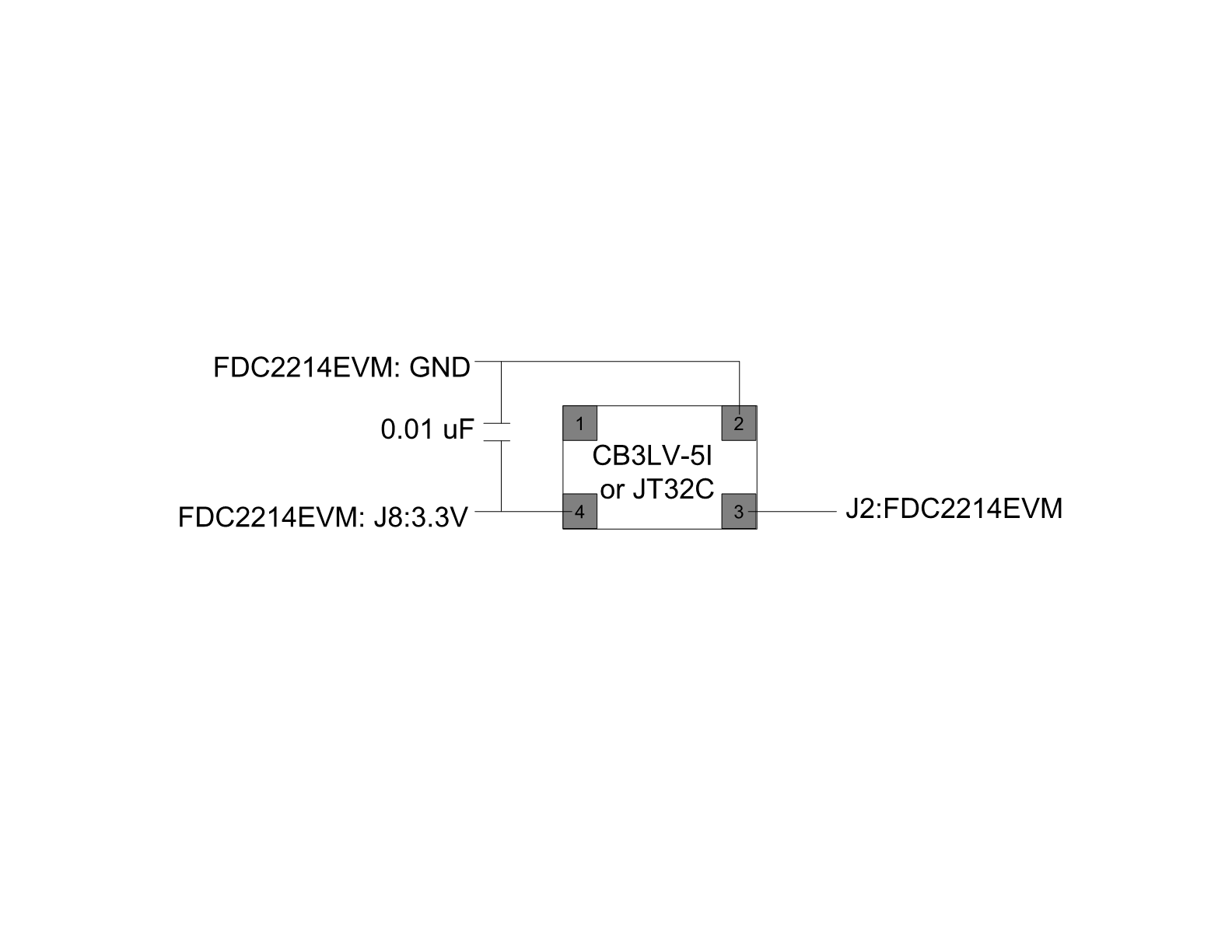
Case 2: with Off-Board oscillator: CB3L-5I-40M0000 (CTS-Frequency Controls)

The red was on when channel 2 and 3 were connected to sensors and channel 0 and 1 were free.

Case 3: with Off-board oscillator O 40.0-JT32C-A-K-3.3-LF (Jauch Quartz)

The green was on when channel 2 and 3 were connected to sensors and channel 0 and 1 were free.

I am confused by the LED indicator statuses. Could someone help?

PS: All sensors are the same having approximately 60-70 pF. All test results look reasonable. 

Regards,

Gu 


  • Hello Gu,

    You can find the meanings of the LEDs in this thread: https://e2e.ti.com/support/data-converters/f/73/t/700086

    In general you don't need to worry about what the LEDs are doing. If you are able to use the GUI and read data from the device, then the LEDs are not important.

    Best Regards,

  • Hi Kristin,

    Thank you for your prompt reply.

    But my observations do not follow the patterns in that thread, e.g. The green LED does not turn off when data is streaming, or the green LED is always on no mater the data is streaming or not. This is the case with the off-board JT32C oscillator.

    By the way, I would like to ask another close related question.

    For the mentioned 2 off-board oscillators, CB3LV-5I (25 ppm stability and 5ps jitter, https://www.ctscorp.com/wp-content/uploads/2015/11/008-0256-0.pdf) and JT32C (2.5 ppm stability and 3 ps jitter, https://www.jauch.com/downloadfile/57ff7db813438_346edabf994d823423fb/jt32c_180424.pdf) ,  I did not see improvement in measurement precision. I checked supply current and output voltage, they both are much lower than the specs. I do not know why?

                                        CB3LV-5I                                                          JT32C

    Supply current               1.8 mA                                                             1.9mA

    Supply current (spec)    20 mA                                                               8mA

    Output voltage               1.53 V                                                              1.62 V

    Output voltage(spec)      > 0.9 Vcc = 0.9*3.3 = 2.97V                          > 0.9Vcc = 2.97V  gg

    Below is my connection illustration. Power supply (3.3V) and ground (GND) were taken from the FDC2214EVM, a 0.01 uF capacitor (10000pF ±5% 100V Ceramic Capacitor C0G) was added in between. The oscillator's output was connected to J2 on the FDC2214, J2 is originally designed for an external off-board oscillator.  Attached is an schematic of the FDC2214EVM. R22 was removed to disable the on-board oscillator 625L3C and R14 was added to enable the off-board oscillator.  The connections were made by soldering short (1-1.5") 24 AWG wires directly on the oscillator. 

    Best regards,

    Gu


  • Hi Gu,

    The strange LED behavior could be because the external oscillator amplitude is too low for the FDC2214 to make reliable measurements. I'm not an expert with these oscillators, but your circuit looks correct to me. For now, I suggest disconnecting the oscillators from the EVM. Use an external power supply to power the oscillators and test their output with minimal output loading. If they are still not behaving properly, then you may need to contact the manufacturer.

    Best Regards,

  • Hi Kristin,

    I used a power regulator,  LP2985AIM5-3.3/NOPB, http://www.ti.com/lit/ds/symlink/lp2985-n.pdf, and hooked it up using the same way as it's schematic of the FDC2214EVM, input power was taken the +5 V at the MSP430 section,  actual  input voltage was 5.15V for the off-board LP2985 and output voltage was 3.62V, I do not know why it's output was not 3.3V, however, the on-board LP2985 can produce 3.3V(actually 3.27V). 

    I got the off-board Oscillator supply current (2.05 mA)  and output voltage (1.67V), which was  slightly higher than it was using the on-board 3.3V power source, probably due to the higher input voltage 3.62V than the 3.27V, however, it is still far below its spec values.

    It is difficulty to understand that both manufactures oscillators behaved the same way. I already contacted the two manufacturers on last Friday and am waiting for their replies.  

    Regards,

    Gu

  • Hi Gu,

    I'm sorry to hear you're still having issues with the oscillators. Hopefully the manufacturers can help. Please let us know if you have any other trouble with the FDC2214.

    Best Regards,