


Other Parts Discussed in Thread: TMS320F28335
Dear Clancy,
In our motor control project we use resolver sensor. In prototype A we encounter no problem after reaching 3000 rpm. The phase currents were really fine. Position feedback also had no problem.
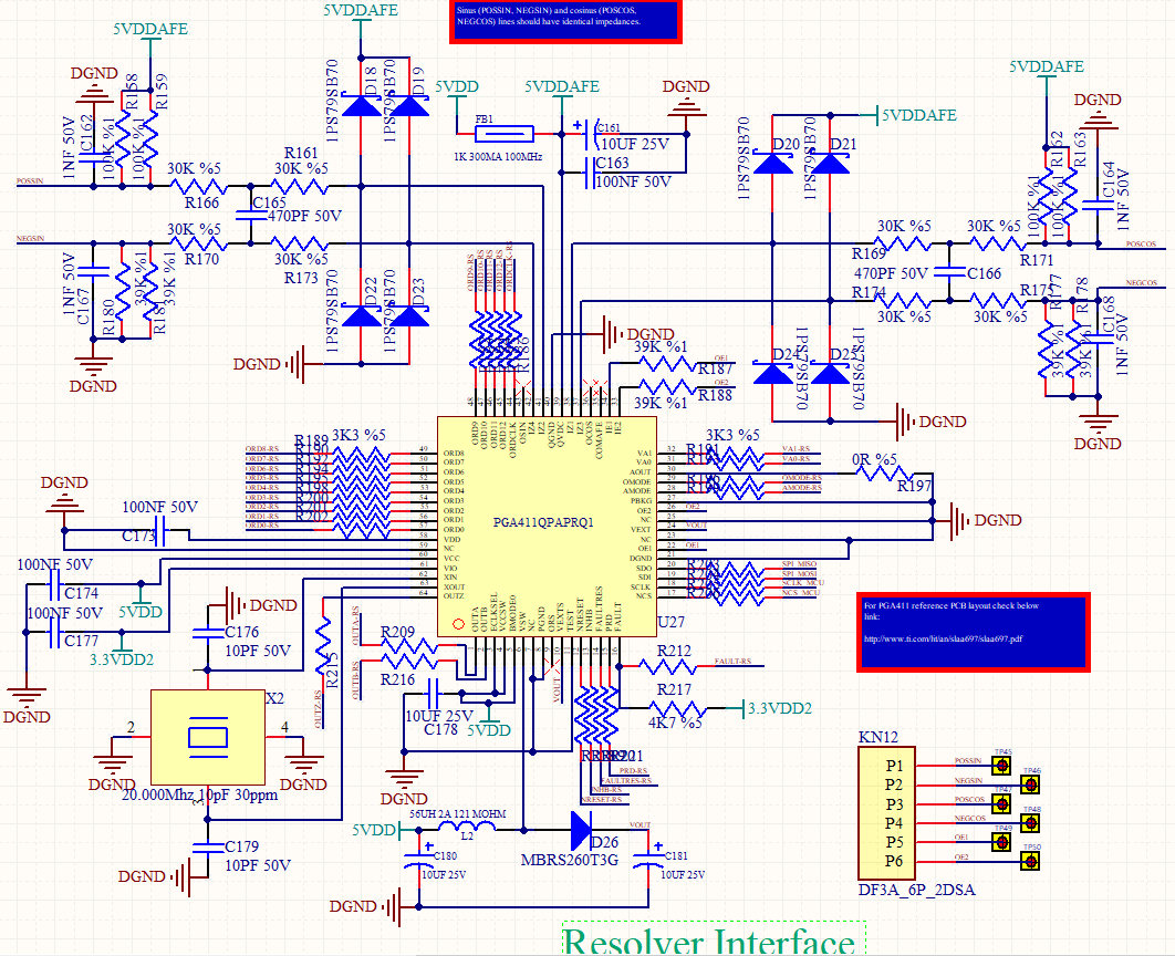
Below please find the schematic of prototype A.
In prototype B, the problem starts when we increase speed. We tried to monitor IZ2 and IZ4 when motoring.
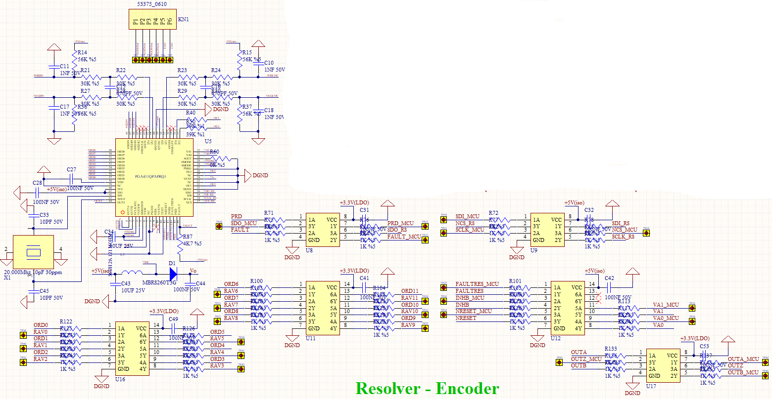
At zero speed. (Yellow: AOUT pin, Blue: IZ2-IZ4 with differential voltage probe)
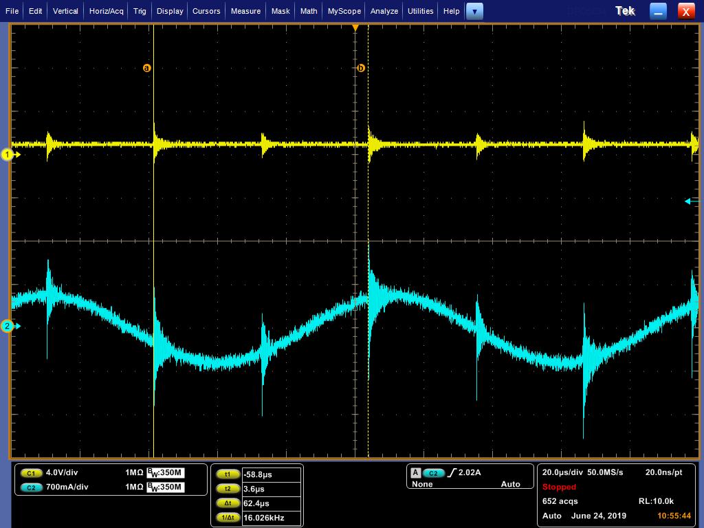
At 200 rpm.
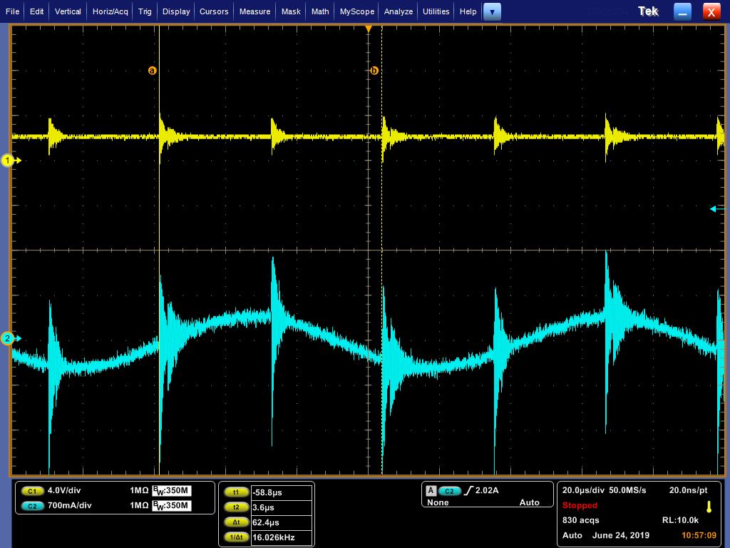
At 1000 rpm below.

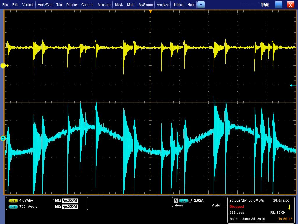
At 3000 rpm.
And the schematic of prototype B is below.
What could be the cause of this increasing noise on sine or cosine interface? Could you help us sort this out? This noise also jeopardize phase current. Waveform of phase current is affected seriouly.
Thanks a lot in advance.
Mert

