Other Parts Discussed in Thread: FDC1004QEVM, , FDC1004
I am currently trying to design an active shield for use with the FDC2214. The datasheet briefly touches on this, but gives no examples or tips:
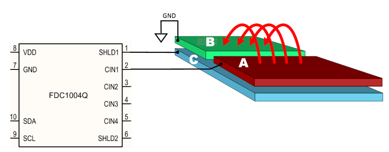
My design uses a custom parallel finger sensor, constructed from etched double-sided PCB material. Instead of liquid level, it will sense the movement of a metal bar in a similar fashion. I first attached my custom sensor to an FDC1004QEVM in the following manner:
This sensor arrangement works very well, and the active shielding truly does direct the electric field as mentioned in the numerous application notes. Despite the great results, the FDC1004Q will not work for my application due to sample speed and resolution. I need the 4ksps and the 28-bit resolution of the FDC2214. Furthermore, my application will be extremely noisy, and the narrow band of the FDC2214 combined with active shielding should give me the best SNR.
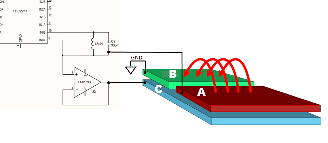
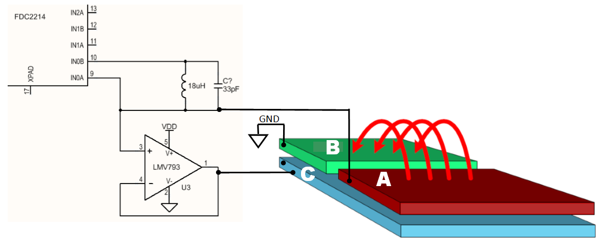
Next, I attached the same custom sensor to the FDC2214EVM. Per the datasheet, I attempted to create an active shield by buffering the INxA signal. My prototype looked like this:
This arrangement performed poorly. The sensitivity was much lower than the first arrangement. When the metal bar was stationary, the data also had much worse noise issues than the FDC1004Q.
So my questions are as follows:
1) Am I doing something blatantly wrong?
2) Are there any reference designs, application notes, schematics, or other documents that deal with adding active shielding to the FDC2214?
3) I have noticed the active shielding output of the FDC1004Q is "stair-stepped." I assume this is a sine wave output from a DAC. The INxA output on the FDCD2214 looks like a half analog sine. Can I ever achieve the same level of active shielding with FDC2214, compared to the FDC1004Q?
Any suggestions are appreciated.
Thank you.