This thread has been locked.

If you have a related question, please click the "Ask a related question" button in the top right corner. The newly created question will be automatically linked to this question.

RTOS/AWR1243: High DC component problem in IF Response (ES2.0 cascaded system)

Part Number: AWR1243

Tool/software: TI-RTOS

Dear Experts,

The system that I'm working on is an AWR1243 ES2.0 with 4chip cascaded radar.

Until now, I just thought the high reflected power from very close range cells are tx-rx leakage of the system or reflection from radar covers.

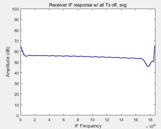
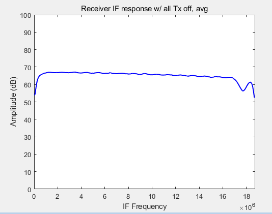
Recently, I saw other thread that shows desired IF response of AWR1243, when all txs are not working.

(https://e2e.ti.com/support/sensors/f/1023/p/663579/2446259)

So I tried same thing with my system, and the result is quite different in terms of DC component.

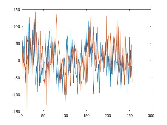
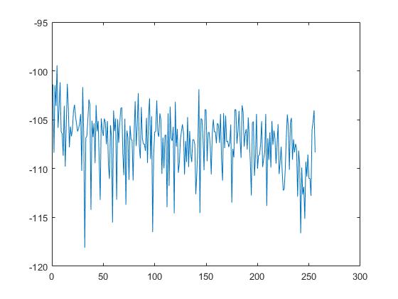
The below result is obtained by raw data streaming and processed in MATLAB with simple FFT and averaging over different antenna channels (total 128).

What can be a root of this problem?

The environment is Processor SDK RADAR 3.4.0 with minor modifications.

The chirp related parameters are:

#define CHAINS_CASCADE_RADAR_SAMPLING_RATE_KSPS     (16666U)
#define CHAINS_CASCADE_RADAR_ADC_START_TIME_IN_US   (6U)
#define CHAINS_CASCADE_RADAR_IDLE_TIME_IN_US        (7U)
#define CHAINS_CASCADE_RADAR_RAMP_END_TIME_IN_US    (38U)
#define CHAINS_CASCADE_RADAR_SLOPE_MHZ_PER_US       (79U)

and the ADC related settings are unchanged from default values of SDK 3.4.0.

(non-interleaved mode, I data first, 16bit, ....)

Best regards,

  • Hello, Any help or suggestion from AWR team will be helpful.

    + additional comments

    After tests, I confirmed that the system can measure the object's range, doppler, angle in ourdoor environment, even if this happens.

    However, the sensitivity of receiver is not good so only corner reflectors can be detected with low SNR...

  • Hi,

    Our cascade expert should be able to review your questions early next week

    thank you

    Cesar

  • Hi,

    I checked if this is solved with increased ADC start time.

    The magnitude of DC component is slightly decreased when the ADC start time is set to 10us, but no big difference.

    Other thing I tried is to take average between ADC samples in one chirp.

    This also shows slight change but no big difference.

    I want some feedbacks from cascade system experts about this issue as form of

    1) possible solution (what we can try)

    2) is it only limited on ES2.0

    3) or nobody experienced/reported this phenomenon

    On the other hand, I found out two signifant issues related cascaded system during tests, and I will post a new thread about new issues.

    (doubled frame period / captured data chip order is changed randomly with parameter change)

    Best regards,

  • Hi Kim,

    DC offset from ADC IQ imbalance is another possible cause of this problem. If you have the TX disabled, then the TX-RX coupling or a short-range "bumper" reflection is probably not the issue. Also, for short-range coupling like TX-RX or bumper, depending on the chirp resolution, you will usually see this peak somewhere in the first few range bins, but not usually the DC bin itself. 

    If you look at the ADC IQ samples, is there a DC offset to the I and Q channels? At least for post-processing, I would recommend estimating the DC with an average of the data over each chirp and subtracting out the average. 

    As for eliminating the offset to begin with, can you please check if the "Enable RX ADC DC offset calibration" option has been set in the AWR_RF_INIT_CALIBRATION_CONF_SB API call prior to RF initialization? 

    For example, using the TI Cascade RF EVM (AWR1243P ES3.0) I have you can see the difference between enabling and disabling RX ADC DC offset cal.

    Below is a single chirp IQ FFT response without RX ADC DC offset cal running. I have all of the TX disabled as well, so TX-RX coupling should not be an issue here. Log scale is dBFS. I see a large DC offset between the IQ samples and a large peak in the zero bin. 

    Same scene, single chirp IQ samples and FFT response after running RX ADC offset cal. 

    Thank you,

    -Randy

  • Hi Kim, 

    And just in case you have not seen the calibration description app note yet: 

    http://www.ti.com/lit/an/spracf4/spracf4.pdf

    Thanks,

    -Randy

  • Dear Randy,

    Thank you for your kind comment.

    I will check whether ADC DC offset calibration is turned on/off, try same thing with you and share the result soon.

    Best regards,

  • Hi Randy,

    I run some tests based on your recommendation, and found out these result.


    However, due to my company restriction in uploading things, I can upload the figures tomorrow.

    1. I found out that the configuration didn't enabled RF INIT CALIBRATION.


    2. After enabling calibration with calEnMask 0x17F0, the power of DC component is decreased significantly in FFT result.


    3. The I/Q data plot shows similar result with your figures. (both before/after calibration)


    4. However, I have still problem and can't get the same result with the figure that I mentioned. 

    (https://e2e.ti.com/support/sensors/f/1023/p/663579/2446259)

    I'm doing some tests and I think its related to HPF setting and IQMM calibration. I will also share this result with you tomorrow.


    One more question. Does IQMM calibration still not recommended to ES2.0 or do we have any other ways or updates?

  • Hi Randy,

    Below figures are the result after enabling boot-up calibration.

    1) calEnMask 0x17F0

    2) calEnMask = 0x7F0 *(IQMM calibration is set to 0)

    HPFs are set to 175/350kHz, and the sampling rate is set to 18750 with complex1x mode.

    I see no big difference between IQMM calibration, but the DC components are still remain.

    After changing HPFs, as you can see below, still there is DC component even if the filter works in low IF region..

    What do you think of this phenomenon?

    Best regards,

  • Hi Kim, 

    Glad to see the cal cleaned things up to some degree. Are you seeing any difference between the master, slave or single-device operation after calibration is applied?

    Thank you,

    -Randy 

  • Hi Randy,

    Unfortunately, I can't see differences between the master/slave chips.

    Since I'm using only radar sdk, I can't verify single-device operation.

    Thank you for your support.

    Best regards,

  • Hi Kim, 

    With the radar SDK you should be able to test out single-device operation. This is setup with the AWR_CHAN_CONF_SET_SB_ICD API command by specifying the CASCADING_CFG field. 

    CASCADING_CFG = 0x0000 -> single device mode

    CASCADING_CFG = 0x0001 -> cascade master device mode

    CASCADING_CFG = 0x0002 -> cascade slave device mode 

    Can you set CASCADING_CFG = 0x0000 and then verify the DC seen?

    Thanks,

    -Randy

  • Dear Randy,

    First of all, I think there are some misunderstanding between us regarding the radar SDK.

    I'm so sorry for confusing expression. What I tried to say was I'm using "Processor RTOS RADAR SDK"

    Until now, I built an appImage with some changed parameters in the massive codes, boot the system and get some raw data by "capture usecase"

    I didn't try operating the cascade system by issuing API commands step by step.

    Therefore, I think I need some time to check this because I need to setup some "API based environment" for our h/w setup.

    Please wait a little.

    Thanks,

  • Hello Randy,

    I checked the IF response in single device mode.

    As you mentioned, there are differences in the IF response between cascading configuration..

    below figure is when I configured the master chip as single device mode, on the same cascade board.

    and I think this IF response is very ideal result.

    Do you think our customized cascaded board has problem?

    Best regards,

  • Hi Kim, 

    Thank you for confirming that. I see the same behavior on the TI Cascade RF EVM. I do not expect this to be a problem - you should be safe just filtering it out in DSP, just like with the larger ADC offset induced DC.

    In cascaded AWRx systems, one additional possible source of DC is leakage from the 20GHz LO sync paths.    

    Thanks

    -Randy

  • Dear Randy,

    Thank you for your kind support.

    Best regards,