This thread has been locked.

If you have a related question, please click the "Ask a related question" button in the top right corner. The newly created question will be automatically linked to this question.

LDC1612: temperature dependent measurement

Part Number: LDC1612
Other Parts Discussed in Thread: LDC1614EVM

Hi,

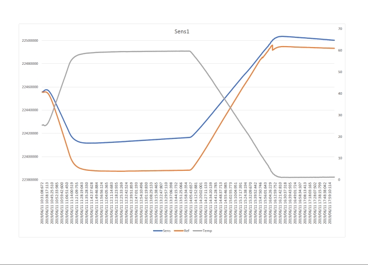
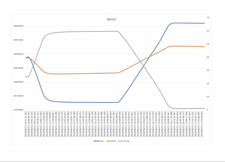
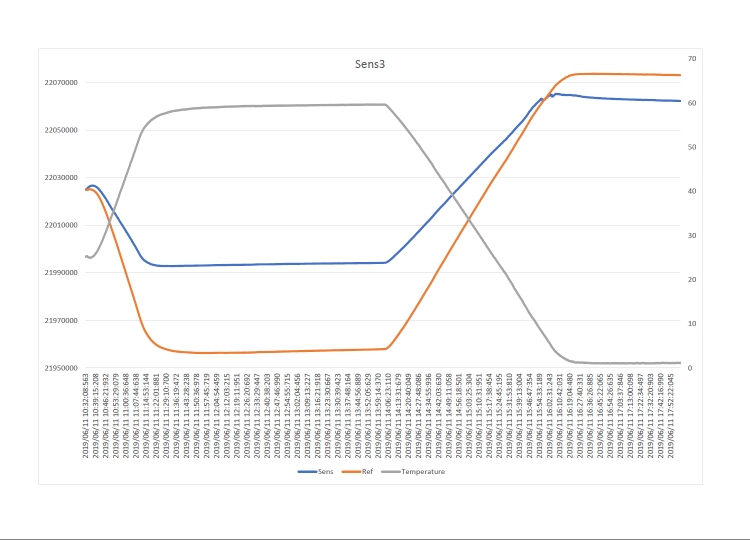
I am using LDC1612 to measure distance of a metal object (shape to be defined) near from one to three millimeters to the coil sensor and I have problems with temperature variation.

A second coil has been provided as a "reference" for compensation of temperature variations. The "main" and "reference" coils have the same designe of LDC1614EVM sensors: 13.9mm, 19 turns/layer, 2 layer, 0.15mm trace width and 0.15mm trace spacing.

The heating tests in a climatic chamber from 0 to 60 ° C on different sensors have given different results with significant differences both as a variation of the "main" channel with respect to the "reference" channel, and between sensor and sensor. The relationship between the "main" channel and the "reference" channel is different for each sensor.
For the test we glued a 1mm plastic spacer and a metal washer (diameter 14mm) on both the "master" and "reference" coils.

Do you have any suggestions or indications for the application and in particular for the best solution to compensate for temperature variations?

thank you

Best Regards,

Samuele


  • Hello Samuele,

    Using the reference coil is the right approach. In general we recommend using a ratiometric measurement between the sensor coil and the reference coil, which provides the most stable response across temperature. 

    Aside from this, we also strongly recommend using C0G/NP0 grade capacitors, which are highly stable across both temperature variation and applied voltage. 

    If a temperature sensor is available, we also recommend calibrating the sensing system across temperature.

    Best Regards,

  • Hello Kristin,

    the capacitors are C0G 5% and there's a temperature sensor on the circuit sensor.

    Below the data collected from the tests of three sensors. You can see how the relationship between sens and ref is different for each sensor.

    The Ref values are normalized with an offset to emphasize the difference between two channels.

    The set of registers are the same for the three LDC1612 and the IDRIVE values ​​are 20 for all.

    The difference of "Conversion Result" start values should be due to the different bonding of the respective targets.

    Do you have, please, a possible explanation for the different behaviour ?

    Best Regards,

    Samuele

    Sensor 1: Conversion Result start value Sens: 22455523 - Conversion Result start value Ref: 23151314 - Offset added to Ref values: -695791

    Sensor 2: Conversion Result start value Sens: 29886082 - Conversion Result start value Ref: 23151314 - Offset added to Ref values : 695791

    Sensor 3: Conversion Result start value Sens: 22025001 - Conversion Result start value Ref: 23355598 - Offset added to Ref values: -1330597

  • Hello Kristin,

    I update the information after performing other tests.
    We have in fact exchanged the capacitors of coil "sens" with those of "ref" and the results are practically the same.
    The two coils are placed side by side and placed at a distance of 1 cm.
    Could it be behavior related to differences in printed circuit boards?
    Could it be useful if I send you the layout of the printed circuit board?

    Thank you
    Best regards
    Samuele

  • Hello Samuele,

    Yes, it's possible that differences in the sensor layout could be causing the frequency changes over temperature. If you are able to share your layout that would be helpful, as well as your schematic. 

    Just to be sure, can you probe INxA or INxB and make sure that the amplitude is between 1.2V - 1.8V? I'd like to make sure that the sensors are oscillating correctly at room temperature.

    Best Regards,

  • Hello Kristin,

    the anomalous behavior was really due to an incorrect adjustment of the current of the iDrive and consequently to a not optimal oscillation voltage. It was less than 1.2 V. Setting it to 1.5 V the system would seem much more stable. I will continue with the tests.

    Thanks for your help

    Best Regards,

    Samuele