This thread has been locked.

If you have a related question, please click the "Ask a related question" button in the top right corner. The newly created question will be automatically linked to this question.

TDC7200: INTB signal doesn't go down

Part Number: TDC7200
Other Parts Discussed in Thread: TDC1000,

Dear TI Experts

 I am using  TDC1000 connected to the TDC7200, and it works well.

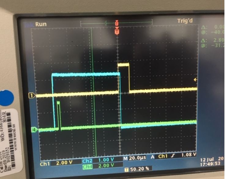
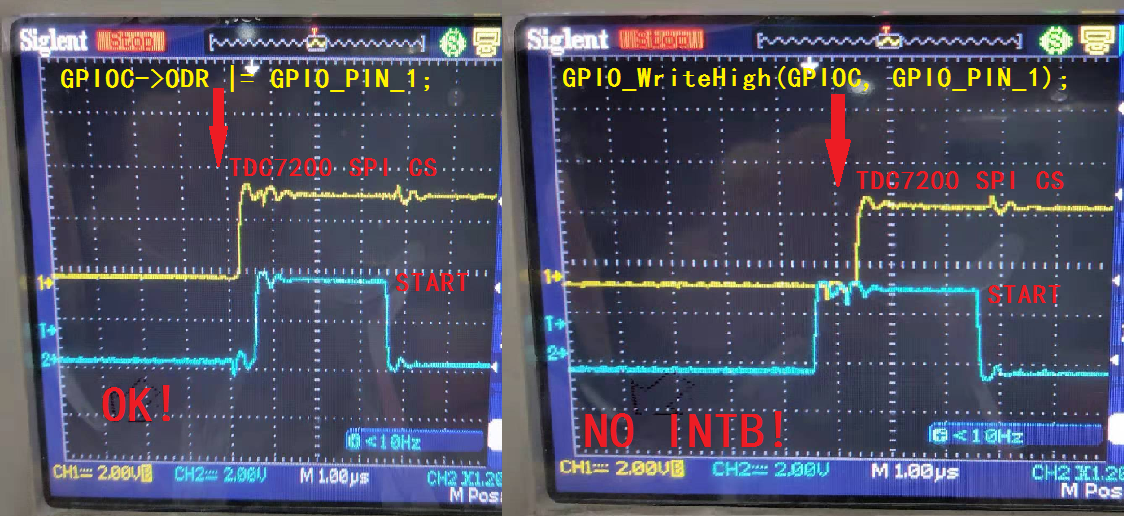
About TDC7200, Their is normal stop signal but sometimes the INTB signal doesn't go down

Can you give me any suggestions about it??Thank you~

  • I also have the same problem.

    Sometimes the TDC1000 has outputs START and STOP, but INTB has no falling edge at START.
     
  • Hello,

    The INTB pin & the TRIGG pin are of similar usage. Please confirm if the TRIGG pin is down post the last STOP signal that is received.

    Also note that the INTB pin is an active low open drain & will require a pull up resistor to Vcc.

    Also it takes a few cycles post the last expected STOP for the INTB pin to toggle. 

  • Hi, Qianqian
    Please refer to the following question, are you also encountering this same problem.
    e2e.ti.com/.../749555
    This question is also answered by "Bharat Aravamudhan", and this problem is not solved.
    TI's "experts" always ask some very bad questions, such as whether to pull up, whether to receive the last STOP, these basic questions we must first rule out before coming here to ask.
    Therefore, basically TI's "experts" never answer questions positively. The final question is no solution. The key is that they still solve the problem as their own solution!

  • e2e.ti.com/.../749555
    This problem has not been solved, because your TDC1000_7200-EVM board uses the standard TOF mode, there is no problem at all, how can you not reproduce this problem!
    There is no problem with customers using short TOF. I suspect that the TDC7200 requires a delay from writing CONFIG1 BIT0 to receive the START, and using a short TOF just circumvents this problem. Or other interference with START and STOP. But actually using the oscilloscope sees START and STOP.
    so Bharat Aravamudhan,
    I will give you a suggestion, it is best to use the customer's board to analyze the problem, or analyze the problem from the hardware direction?

  • Hello Bharat

    Yes, the INTB is pulled up resister to VCC~

    Is their a timing requirment of start/stop/INTB?

     About the layout, my start & stop signal is not equal in length ,I have no idea if it's affact the INTB

  • Hello ,

    Very urgert case

    Really need your suggertion~~

  • Qianqian,

    The INTB pin goes low after a few clock cycle post the last expected STOP signal.

    However in case you expect 5 STOP signal and receive only say 3 STOP signal then there could be an issue of the INTB pin not toggling.

    The START & STOP signal need not be of equal length and this will not affect the INTB pin as well.

    We recommend have a 10k ohm pull up resistor at the INTB pin though.

  • Dear Bharat 

    Yes, we have a 10k ohm pull up resistor at the INTB pin ·

  • Qianqian,

    Please confirm if you are using the TDC1000-TDC7200EVM, I have attached a register map for this EVM wherein we have a 1Mhz transducer connected to a plastic container to measure its level. I have also attached the plot for START, STOP & INTB that we observe in our lab here with this EVM. The Green is START, Yellow is STOP & Blue is INTB.

    TDC1000_Config0                         00
    TDC1000_Config1                         00
    TDC1000_Config2                         00
    TDC1000_Config3                         00
    TDC1000_Config4                         00
    TDC1000_TOF-1                           00
    TDC1000_TOF-0                           00
    TDC1000_Error_Flags                     00
    TDC1000_Timeout                         00
    TDC1000_Clock_Rate                      00
    TDC1000_Conts_Trigger                   00
    TDC7200_Config1                         00
    TDC7200_Config2                         00
    TDC7200_Interrupt_Status                00
    TDC7200_Interrupt_Mask                  00
    TDC7200_Coarse_Cntr_Ov_H                FF
    TDC7200_Coarse_Cntr_Ov_L                FF
    TDC7200_Clock_Cntr_Ov_H                 FF
    TDC7200_Clock_Cntr_Ov_L                 FF
    TDC7200_Clock_Cntr_Stop_Mask_H          00
    TDC7200_Clock_Cntr_Stop_Mask_L          00
    TRIGGER_UPDATE_FREQ                     0001
    TDC_AVG/STDEV_NUM_ELEMS                 000A
    SAVE_GRAPH_DATA_TO_FILE                 00
    FLOW_MODE_SELECT                        00
    Y-SCALE_CENTER                          0032
    X-SCALE_RANGE                           0032
    MEASURE_RTD1                            00
    SAVE_RESULT_REGR_TO_FILE                00
    GRAPH_MULTI_STOPS                       00
    TDC_SELECT                              00
    TEMP_RTD_SELECT                         00
    TEMP_RTD_MODE                           01
    TEMP_AVG/STDEV_NUM_ELEMS                000A
    SAVE_TEMP_DATA                          00
    GRAPH_YMAX_DATA                         00000000004C4B40
    GRAPH_YMIN_DATA                         0000000000030D40
    TDC1000-HV_DRV_EN1                      00
    TDC1000-HV_DRV_EN2                      00
    HV_DRV_EN1_Period                       001E
    HV_DRV_EN2_Period                       001E
    ENABLE_POWER_CYCLE                      00
    CLK_FREQ_(1-16MHz)                      8.000000
    CLK_SOURCE_SEL                          00
    CPU_CLK_FREQ                            05
    CPU_CLK_EN                              00
    TDC1000-HV_BST_PWR_EN                   00
    HV_BST_PWR_EN_Period                    0000
    FWD2REV_FLOW_DELAY                      0000
    TDC1000-IMPE_MATCH_EN                   00
    ENABLE_UART_STREAM                      00
    ENABLE_MSP430TIMER_TDC                  00
     

  • Another useless reply, your reply is normal. Using the TDC1000-TDC7200EVM is a problem that cannot be reproduced by users. stubborn!

    One cannot explain the problem clearly, and one cannot answer the question correctly!
    Don't you look at this post?

    e2e.ti.com/.../749555

    The SHORT TOF is ok, The standard TOF has problems on the user's board!
    There is no problem with the TDC1000_7200-EVM board standard TOF!

  • Mao,

    Please help me understand your case better. Do you have issues with Standard ToF ? What is your condition when the INTB does not toggle. Please start a separate thread or continue from any of your own thread.

    Qianqian,

    Please let me know if my register map helped your setup case.

  • I have been having the same problem with INTB for the last week. I have two different design boards using different processors, One works ok, the other does not assert INTB.

    I found that the IDLE states of the SPI bus were the problem. The working board has an idle state logic 0, the non-working board and idle state of logic 1. Communication however was ok on both boards and the START and STOP signals were correctly asserted.

    Ensure your idle states are logic 0.

    I keep checking, as I could not believe this was the problem.

    Geoff

  • Geoffrey,

    Thanks for providing inputs as for the cause for INTB not showing up, we will now need to check if this is a real case as well.

  • Thank you Geoff.

    The problem is solved, as shown below:

    As shown below, this is why there is no problem with SHORT TOF.

    I think the TDC7200 design is not perfect.