This thread has been locked.

If you have a related question, please click the "Ask a related question" button in the top right corner. The newly created question will be automatically linked to this question.

IWR1642: Unexpected ADC data

Part Number: IWR1642
Other Parts Discussed in Thread: , IWR1443

Hello everyone!

I'm trying to capture FMCW chirps, but for some reason the only thing I can get is this plot (same for all 4 rx antennas and  2 long chirps in configuration).

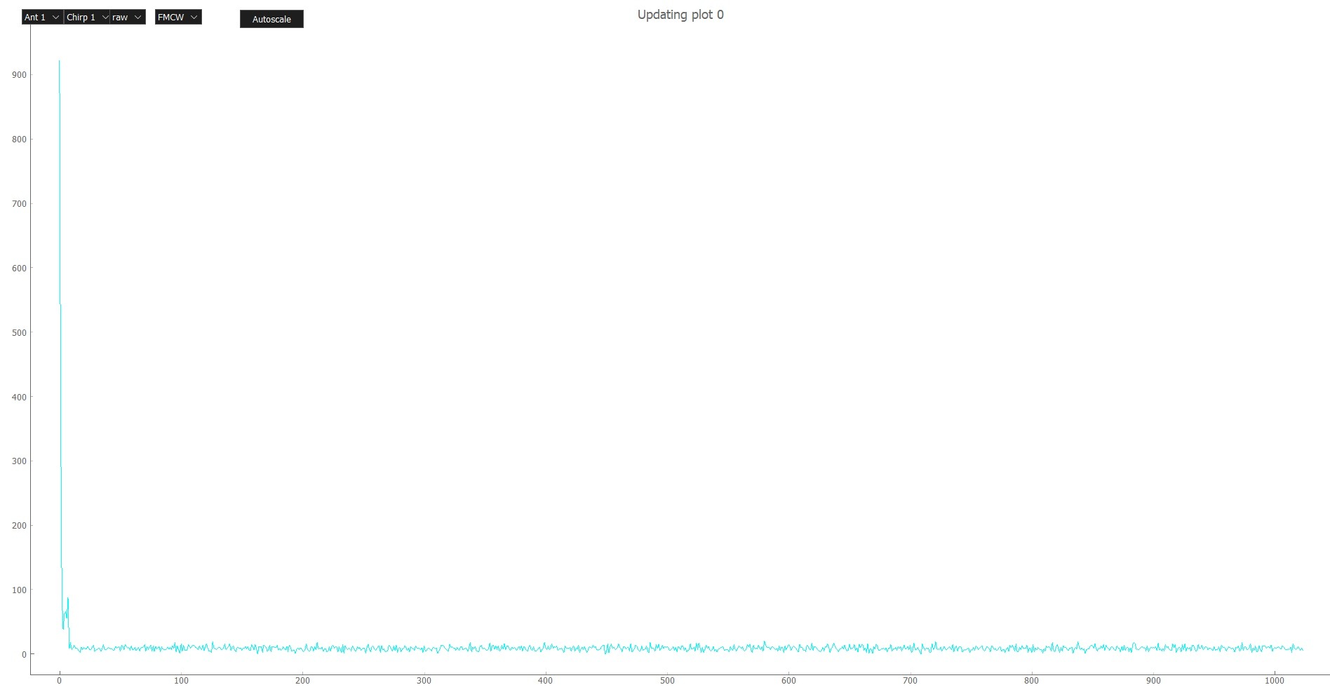
X axis -- sample number
Y axis -- sqrt(I^2+Q^2)

So, for some reason I got spike on first sample, some samples with abs values in ~50-100 range and tail is Gaussian noise near zero.

I expected sine-like waveform which I can use for further processing. This picture was plotted by script on my PC. Capture chain was simplified to ADC -> eDMA -> DSS L3 (shared with master) -> MSS SPI w/ DMA -> PC, so pretty much everything is done by hardware without the use of CPU resources.

My troubleshooting attempts included: usage of memcpy/memmove instead of eDMA, using UART over SPI (even dumb printfs with data straight from ADC buffer), HSRAM instead of L3. In all cases results were the same. Tested both on custom board and on IWR1642BOOST.

We use custom configuration sequence with mmwavelink and modified cli commands from demo, but this file contains our configuration converted into SDK Demo format.

 4034.config_modified.cfg

Any thoughts on what can be wrong with ADC data? 

Regards,

Ivan

  • Hi Ivan,

    The DCA1000 board is the supported solution for raw data capture with the IWR1642.

    Best,

    Chloe

  • Thank you for your answer, Chloe.

    Unfortunately my customer was not able to purcase this board, I suppose because of customs, for some reason its not on the list of electonics allowed to import.  

    On the other hand, we want to process this data with DSP in production. And not the capture of raw data is what I'm interested in, I saw enough raw data before, I want to know what can be the problem with chirp characteristics/ADC/ADC buffer in case of 2 last chirps in the sequence. I don't want to get samples out of the SoC, I want to process them inside. No use for the capture board in this case. If the board is the only way to capture data -- there is no use for DSP, or any accelerator, just dumb interface to dump it out.

    I see samples from first 1024 chirps and they are perfect, but 2 last chirps seem to be captured wrong. I'm sure I configured the buffer right, 1 chirp threshold at ping / 1 chirp threshold at pong / 2048 IQ samples per chirp and 4 RX channel offsets set to 0,0x2000,0x4000,0x6000, so whole 32k buffer is used for one chirp.

    P.S. The board is quite overpriced, 500 USD for cheap lscc fpga, 2xDDR chips, 2xFTDI, 802 PHY and some SMD's is fun price (even if you paid lot for fpga IP's, they are cheap in case of Lattice). So far, addition of FPGA into the design will raise production cost bout 2 times, since IWR1642 are ~19k USD per 1k reel. Customer made decision for 1642 SoCs, as long as they can do all the processing onboard. Imho (not the customer opinion), implementation of radar on IWR1443 (or even on one without hardware accelerator) w/ CSI2 and lscc fpga will allow us to achieve insane frame rate and accuracy. But I quickly dumped this idea because of buffer bottlenecks of IWR1443. I would like to get more memory to store my samples in ;C

    P.P.S. Sorry about my "life story"