This thread has been locked.

If you have a related question, please click the "Ask a related question" button in the top right corner. The newly created question will be automatically linked to this question.

PGA460-Q1: Always receive a echo signal when using bi-static transducer pair [a separate transmitter and receiver]

Part Number: PGA460-Q1
Other Parts Discussed in Thread: PGA460, MSP-EXP430F5529LP, ENERGIA, BOOSTXL-PGA460,

Hi team,

I tried to use a bi-static transducer pair [a separate transmitter and receiver] with PGA-Q1. I followed the instructions on the datasheet: desolder the 0-Ω resistor at R36 and connect the receive-only transducer to the J14 socket. 

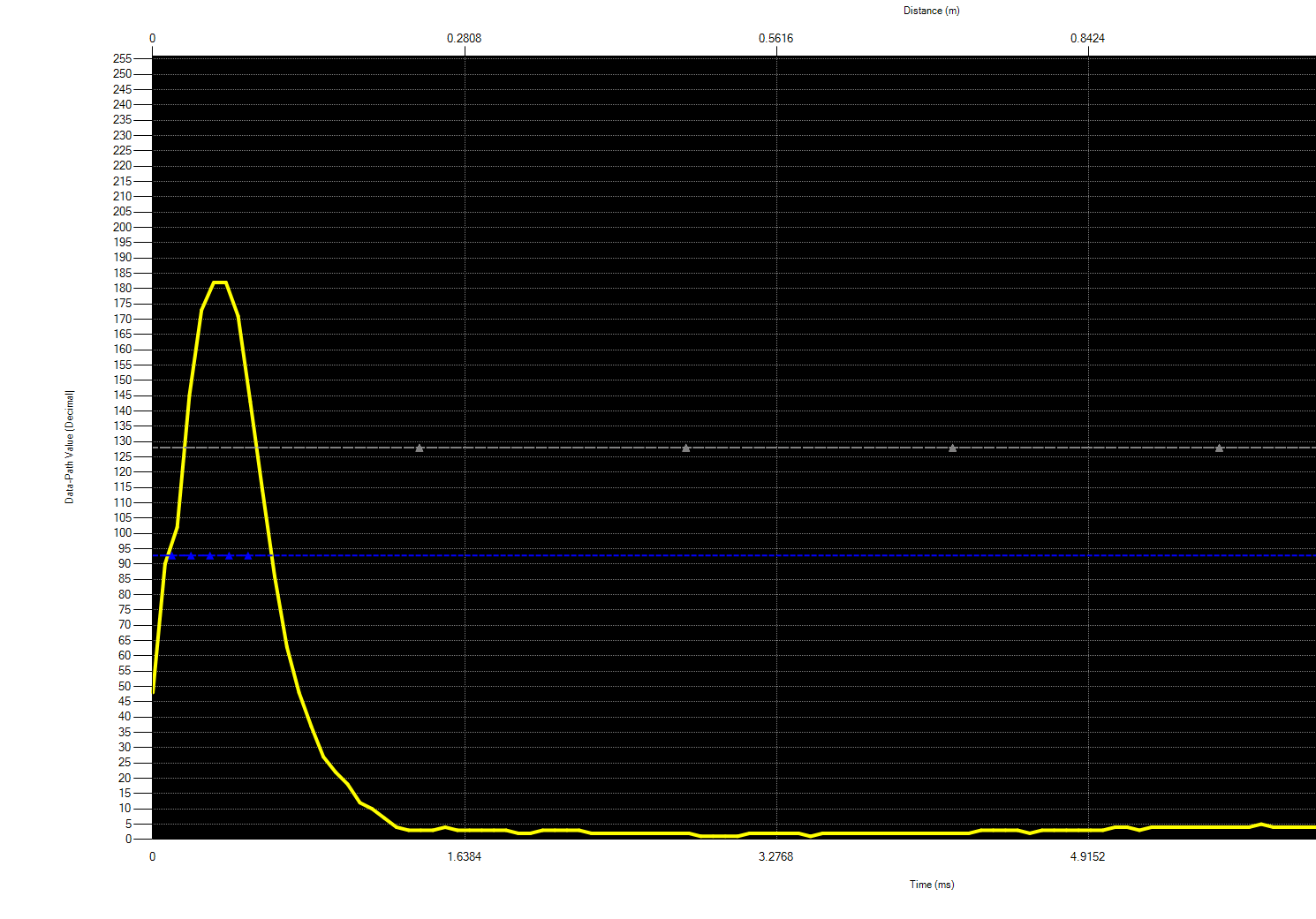
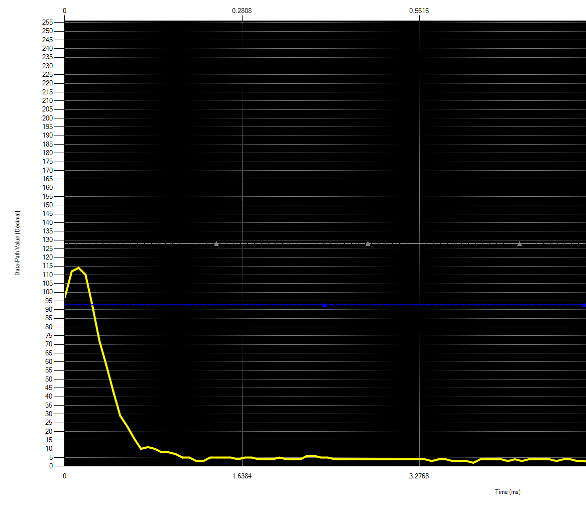
However, when I used the GUI program to check the echo signal, I can always find a initial burst signal no matter where I put the receiver (e.g., even not facing transmitter). I am wondering if there is a setting that can set the transmitter to burst and let the receiver only listen for the signal?

  • Hi Jun,

    Is the burst signal weaker in amplitude in the bi-static configuration when compared to the mono-static configuration? Also, is it consistent in amplitude?

    It is possible that the burst signal is appearing on the receiving due the electrically coupled burst noise inside the device. This is why the orientation of the receiver is not making much of a difference because the burst coupled noise is not acoustic. I recommend that you keep the initial time varying gain low to minimize the electrically coupled burst energy shown at the front end.

  • Hi Akeem,

    Thanks for the quick reply. 

    Is the burst signal weaker in amplitude in the bi-static configuration when compared to the mono-static configuration?

    - I don't think so. The following image shows the signal when I put the receiver far far away from the transmitter and default short range setting is used. 

    Also, is it consistent in amplitude?

    - Yes, it is quite consistent. 

    Since I am trying to see if the ultrasonic signal can be transmitted through a table made of wood (e.g., put two transducers facing the table ), the echo signal that I am interested might lie in 0.1ms ~ 0.2ms. Any idea that I can get a "clean" receiver? 

    What if I use two chips? One for bursting, the other for listening. But how to sync the signals?

  • Jun,

    If you remove the transmitter, what does the echo data dump look like then?

    To ensure the transmitter is acoustically isolated from the return path, can you probe receiving transducer's positive terminal to ensure the burst pulses do not appear?

    Yes, you can use two PGA460 devices to completely isolate the transmitter and receiver. I have released a recent app note which demonstrates how to use and synchronize two PGA460s on the same UART/SPI/OWU bus, such that one bursts and the other only listens. You can see this implementation discussion in the PGA460 Array of Ultrasonic Transducers for Triangulation and Tracking app note, section 3.1 Transceiver and Receiver. You'll effectively need to use the broadcast burst-and-listen command set, but ensure the receiving module's OUTA/B pins remain floating to effectively listen only.

  • Hi Akeem,

    I can still find the burst signal after I removed the transmitter but the signal is smaller. 

    Thus, I guess it is the combination of air-coupled signal and "electrical noises"?

    Any suggestions on how to capture an echo signal in 0.1ms ~ 0.2ms considering this "dominant" effect? 

  • Hi Jun,

    On the receiver settings, I recommend that you minimize the initial time varying gain (i.e. 32.5dB) to mask the electrical noise coupling in the device, then quickly ramp up to your desired TVG level. On the driver settings, the number of pulses has the strongest effect on the internal coupling noise; ensure you have minimized the number of pulses to prevent electrical burst noise peaking.

    The acoustic signal can usually amplify to a level greater than that of the electric burst coupling noise, so you should be able to detect between 0.1~0.2ms using a bi-static configuration. Here are some example results:

  • Hi Akeem, 

    I plan to synchronize two PGA460s using the default launchpad (e.g., MSP-EXP430F5529LP). I found your triangulation example and Energia codes but I am wondering how to connect two PGA460s to the launchpad? Simply stack them together? And then download the codes to the launchpad? Thanks!

    Jun

  • Hi Akeem,

    Another question came up when I checked your Energia codes (e.g., Triangulation.ino). I noticed that you set two transducers into burst and listen mode instead of one burst and listen mode and the other listen only mode. I am wondering why? 

    And you also mentioned to set OUTA and OUTB "float" on the receive-only transducer. I am wondering what this "float" means? Simply not connect OUTA and OUTB to the mother board? 

    Looking forward to your reply. 

    Best,

    Jun 

  • Part Number: PGA460-Q1

    Hi Akeem, 

    I plan to synchronize two PGA460s (one as transceiver/ the other receiver only) using the default launchpad (e.g., MSP-EXP430F5529LP). I found your triangulation example and Energia codes but I am wondering how to connect two PGA460s to the launchpad? Simply stack them together? 

    Another question came up when I checked your Energia codes (e.g., Triangulation.ino). I noticed that you set two transducers into burst and listen mode instead of one burst and listen mode and the other listen only mode. I am wondering why? 

    And you also mentioned to set OUTA and OUTB "float" on the receive-only transducer. I am wondering what this "float" means? Simply not connect OUTA and OUTB to the mother board? 

    Looking forward to your reply.

    Jun

  • Hi Jun,

    Because the triangulation code relies on a bus topology (through the PGA460's UART, SPI, or OWU; I will use UART as an example in this discussion), you will need to either stack two BOOSTXL-PGA460 modules so that the RXD pins are common and the TXD pins are common, or use jumper wires.

    It is crucial that you pre-program the UART_ADDR of each device to a different value (i.e. Slave A is UART_ADDR=0x0 and Slave B is UART_ADDR=0x1). If both are the same address, and you connect them both to the bus, you will not be able to communicate with either PGA460 device.

    Once you have pre-configured the BOOSTXL-PGA460 register settings and UART_ADDR independently / one-at-a-time, you can then stack them, and load the Energia triangulation code onto the LaunchPad. 

    In this case, you should decouple the OUTA and OUTB pins (float / disconnect) them from Slave B, so that when you send a broadcast burst+listen command to all devices on the UART bus, Slave B will physically be unable to transmit an echo. Instead, Slave B will effectively use the broadcast burst+listen command and a broadcast listen only command. This keeps both Slave A and Slave B synchronized in time for accurate triangulation.

  • Hi Akeem,

    Thanks for your detailed explanation. I am wondering what is the easiest way to set the UART_ADDR of each device? I tried to use the EVM to set up (e.g., Update Device to Selected Addr), just like the following figure:

    It worked at the first beginning since I could see the address changed on the EVM Status:

    But after I removed the BOOSTXL-PGA460 and inserted back, the address just changed back to 0. I am wondering how to set the address permanently?

  • Jun,

    After you update the UART_ADDR using the "Update Device to Selected Addr" button, you need to EEPROM burn the device to save the new value of UART_ADDR. UART_ADDR is a user EEPROM value. To burn the EEPROM, go the the Test Mode page of the GUI, and click the "Program EEPROM" button. Note, clicking this button will save all EEPROM values, so any other changes you make to this registers will also be saved.

  • Hi Akeem, 

    Thanks for you quick reply. It worked! I can get the data from two transducers now. 

    But with default setting, the calculated distance from receive-only transducer seem inaccurate (the transceiver seems accurate). It always returns a number around 2 no matter where I put the object. Any idea why?

    And I plan to track a object at about 10~15cm away from the transducers, is it possible? I am wondering how I should set those parameters? 

    Thanks,

    Jun

  • Hi Jun,

    You will need to optimize the settings and threshold for both the transceiver and receiver modules using the PGA460-Q1 EVM GUI. The default settings and fixed threshold level may not suffice for the triangulation demo.

    Once you have a valid object #1 ultrasonic measurement result, the triangulation algorithm's law of cosines calculation will return a degree value. See the following working example of the triangulation.ino demo when the modules are separated by 9 inches, and both are pointed upwards at a ceiling at ~2.2m.

    Here are the GUI echo data dump outputs captured prior to running the demo.

    Transceiver EDD Receiver EDD