This thread has been locked.

If you have a related question, please click the "Ask a related question" button in the top right corner. The newly created question will be automatically linked to this question.

AWR1642BOOST: 2D FFT Results - symmetric errors

Part Number: AWR1642BOOST
Other Parts Discussed in Thread: AWR1642

Hi,

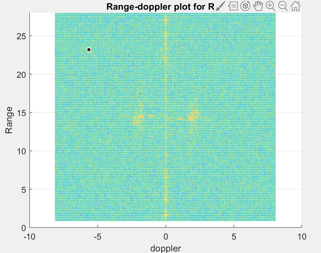
I found my 2DFFT results have some symmetric patterns which should be wrong according to the post processing results of mmwave studio.

Let's see an example. This 2 images are 2DFFT result from same complex data which is captured by DCA1000 and AWR1642. The left one is what I plot and the right one is what mmwave studio plot.

At approximatelt 15m, there are two doppler patterns in the left image, however there is only one positive pattern in right figure.

I don't know why my code would generate this error and it seems your matlab code is more robust. Do you hava any idea of how to solve this problem?

Thanks,

William


  • Hi,

    Could you post your configuration and code (pseudo) of the script?

    Regards,

    Jitendra

  • Sure!

    The configuration is shown below. And the matlab pseudo code is something like:

    clc;
    clear all;
    close all;
    %% parameter setting
    % constant parameters
    c = physconst('LightSpeed');% Speed of light in air (m/s)
    fc = 77e9;% Center frequency (Hz)
    lambda = c/fc;
    Rx = 4;
    Tx = 2;

    % configuration parameters
    Fs = 4*10^6;
    sweepSlope = 21.0017e12;
    samples = 128;
    loop = 255;
    % loop = 128;
    Tc = 120e-6; %us
    fft_Rang = 128;
    fft_Vel = 256;
    data_each_frame=samples*loop*2*Rx;
    %% Creat grid table
    freq_res = Fs/fft_Rang;% range_grid
    freq_grid = (0:fft_Rang-1).'*freq_res;
    rng_grid = freq_grid*c/sweepSlope/2;% d=frediff_grid*c/sweepSlope/2;

    % velocity_grid
    dop_grid = fftshiftfreqgrid(fft_Vel,1/Tc); % now fs is equal to 1/Tc
    vel_grid = dop_grid*lambda/2; % unit: m/s, v = lamda/4*[-fs,fs], dopgrid = [-fs/2,fs/2]

    w = [-180:4:180]; % angle_grid
    agl_grid = asin(w/180)*180/pi; % [-1,1]->[-pi/2,pi/2]

    %% read file
    data=readDCA16xx('adc_data.bin');
    data_all=reshape(data,size(data,1)*size(data,2),[]); % reshape 4 channels into 1
    for i=1:10 % 1:end frame
    % seperate each frame and reshape the raw data to foramt [samples,antennas,chirps]
    Framedata(:,i)=data_all(((i-1)*data_each_frame+1):i*data_each_frame);
    Frame_loop(:,:,i)=reshape(Framedata(:,i),samples*4,[]);
    Frame_loop_chirp1(:,:,i)=Frame_loop(:,1:2:end,i);
    Frame_loop_chirp2(:,:,i)=Frame_loop(:,2:2:end,i);

    for jj=1:loop
    Frame_loop_chirp1_Rx(:,:,jj,i)=reshape(Frame_loop_chirp1(:,jj,i),[samples Rx]);
    Frame_loop_chirp2_Rx(:,:,jj,i)=reshape(Frame_loop_chirp2(:,jj,i),[samples Rx]);
    end
    Xcube_chirp1=permute(Frame_loop_chirp1_Rx(:,:,:,i),[1 2 3]);
    Xcube_chirp2=permute(Frame_loop_chirp2_Rx(:,:,:,i),[1 2 3]);

    Nr=size(Xcube_chirp1,1); %%% length of Chirp
    Ne=size(Xcube_chirp1,2); %%% # of receiver
    Nd=size(Xcube_chirp1,3); %%% # of chirp loop
    % Range FFT
    for ri=1:Ne
    for rj=1:Nd
    win_rng = Xcube_chirp1(:,ri,rj);
    Rangedata(:,ri,rj)=fft(win_rng,fft_Rang);
    end
    end
    % Doppler FFT
    for di=1:Ne
    for dj=1:Nr
    win_dop =reshape(Rangedata(dj,di,:),Nd,1).* 1;%hann(Nd);
    DopData(dj,di,:)=fftshift(fft(win_dop,fft_Vel));
    end
    end
    % plot 2DFFT
    figure()
    mesh(vel_grid,rng_grid,20*log10(abs(squeeze(DopData(:,1,:)))));
    view(0,90)
    axis([-10,10,0,28])
    title('Range-doppler plot for Rx1')
    xlabel('doppler')
    ylabel('Range')
    end:

    The read_DCA16xx function is :

    %%% This script is used to read the binary file produced by the DCA1000
    %%% and Radar Studio
    %%% Command to run in Matlab GUI - readTSW14xx('<ADC capture bin file>')
    function [retVal] = readDCA16xx(fileName)
    %% global variables
    % change based on sensor config
    %----------------------------------------------------------------------
    numADCBits = 16; % number of ADC bits per sample
    numLanes = 2; % do not change. number of lanes is always 4 even if only 1 lane is used. unused lanes
    isReal = 0; % set to 1 if real only data, 0 if complex dataare populated
    % with 0
    %----------------------------------------------------------------------
    %% read file and convert to signed number
    % read .bin file
    fid = fopen(fileName,'r');
    adcData = fread(fid,'uint16');
    % compensate for offset binary format
    adcData = adcData-2^15;
    % if 12 or 14 bits ADC per sample compensate for sign extension
    if numADCBits ~= 16
    l_max=2^(numADCBits-1)-1;
    adcData(adcData>l_max) = adcData(adcData>l_max) - 2^numADCBits;
    end
    fclose(fid);
    %% organize data by LVDS lane
    % reshape data based on four samples per LVDS lane
    len_total = length(adcData);
    fix_adc_len = len_total - rem(len_total, numLanes*4);
    adcData = reshape(adcData(1:fix_adc_len), numLanes*4, []);
    % for real only data
    if isReal
    %each LVDS lane contains two samples from each RX
    rxSample1 = adcData([1,2,5,6],:);
    rxSample2 = adcData([3,4,7,8],:);
    % interleave the first sample set and the second sample set
    adcData = reshape([rxSample1;rxSample2], size(rxSample1,1), []);
    %for complex data
    else
    % combine real and imaginary parts of complex number
    adcData = adcData([1,2,5,6],:) + sqrt(-1)*adcData([3,4,7,8],:);
    end
    %% return receiver data

    retVal = adcData;

    Thanks,

    William

  • Thanks,

    I solved  this problem. It is because I read dca1000 functoion was wrong. I used the new function in fiile 'Mmwave Radar Device ADC RAW data capture' and it works now.

    William