


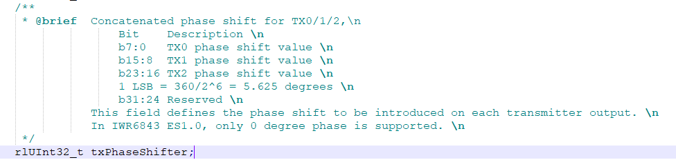
We want to use TX phase shift on AWR1843. In the picture attached is a part of rl_sensor.h from mmwave SDK 03_02_00_04.
It says that phase shift value for all TX antennas is 8bit data. Is it signed or unsigned value? I suppose phase shift goes from -90 to 90 possibly.
I understand you used it for AWR1243P but it says that can be used for AWR1843 with txPhaseShifter field in profile Config.
As it is described in document: http://www.ti.com/lit/ug/tiduen5/tiduen5.pdf Imaging Radar Using Cascaded mmWave Sensor Reference Design (pages 12/13)
it says that when 2*lambda is between TX antennas, we have 0, 4pi*sin(theta), 8pi*sin(theta),... and that is clear. But is not clear for example how 32*pi*sin(theta) will be written into 8bit register.
( Unless you subtract n*360 ? )
TX0: 0 is written in register of first TX antenna.
TX1: 4pi*sin(theta) and theta = 30deg in register we need to write: integer(4pi*sin(30) * 180/pi / 5.625 = 64), 64 is written in register of second TX antenna?
TX2: 8pi*sin(theta) and theta = 30deg in register we need to write: integer(8pi*sin(60) * 180/pi / 5.625 = 221), 221 is written in register of third TX antenna?
What about negative angle for beam steering? If we want for example -45 degrees, 4pi*sin(theta) and 8pi*sin(theta) are negative, what to do then?
Short explanation about data formats should be a good answer to the question.
Regards,
Predrag
