


Other Parts Discussed in Thread: AWR1243
Hi, I am using the AWR1243BOOST evaluation module with a MMWAVE DEVPACK and a custom adapter board on a Xiling Zynq Evaluation Board ZCU102. I can successfully read data on the LVDS Stream, which i checked with the test pattern generator of the AWR1243, controlled via the MMWAVE DEVPACK and the DFP Version 1.02.
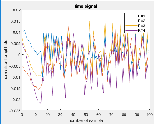
However, if I configure the AWR1243 device for radar operation, only the first 16 samples seems to be correct. I get this error as well with my customized config file
#
#For detailed view of mmWave Radar configuration structure
#please refer
#ti\control\mmwavelink\docs\doxygen\html\index.html
#

#
#cascade mode enable
#
cascade_enable=0;
#END

#
#power on master arguments, please modify if needed.
#rlClientCbs_t: crcType 0:16Bit/1:32Bit/2:64Bit, ackTimeout
#
crcType=0;
ackTimeout=1000;
#END

#
#channel config parameters, please modify if needed.
#rlChanCfg_t
#
channelTx=3;
channelRx=15;
cascading=0;
#END

#
#ADC out config parameters, please modify if needed.
#rlAdcOutCfg_t
#
adcBits=2;
adcFormat=0;
#END

#
#DATA format config parameters, please modify if needed.
#rlDevDataFmtCfg_t
#
rxChanEn=15;
adcBitsD=2;
adcFmt=0;
iqSwapSel=0;
chInterleave=0;
#END

#
#Low power config Paramters, please modify if needed.
#rlLowPowerModeCfg_t
#
anaCfg=0;
lpAdcMode=0;
#END

#
#Data Path config parameters, please modify if needed
#rlDevDataPathCfg_t
#
intfSel=1;
transferFmtPkt0=1;
transferFmtPkt1=0;
cqConfig=2;
cq0TransSize=64;
cq1TransSize=64;
cq2TransSize=64;
#END

#
#LVDS clock config parameters, please modify if needed
#rlDevDataPathClkCfg_t
#
laneClk=1;
dataRate=2;
#END

#
#SET HSI clock parameters, please modify if needed.
#rlDevHsiClk_t
#
hsiClk=5;
#END

#
#LANE config parameters, please modify if needed.
#rlDevLaneEnable_t
#
laneEn=15;
#END

#
#LVDS Lane Config parameters, please modify if needed.
#rlDevLvdsLaneCfg_t
#
laneFmtMap=0;
laneParamCfg=0;
#END

#
#Profile config parameters, please modify if needed.
#rlProfileCfg_t
#
profileId=0;
startFreqConst=1435384035;
idleTimeConst=800;
adcStartTimeConst=100;
rampEndTime=4200;
txOutPowerBackoffCode=0;
txPhaseShifter=0;
freqSlopeConst=986;
txStartTime=-400;
numAdcSamples=722;
digOutSampleRate=37500;
hpfCornerFreq1=0;
hpfCornerFreq2=0;
rxGain=30;
#END

#
#Chirp Configuration parameters, please modify if needed.
#rlChirpCfg_t
#
chirpStartIdx=0;
chirpEndIdx=1;
profileIdCPCFG=0;
startFreqVar=0;
freqSlopeVar=0;
idleTimeVar=0;
adcStartTimeVar=0;
txEnable=2;
#END

#
#Frame configuration parameters, please modify if needed.
#rlFrameCfg_t
#
chirpStartIdxFCF=0;
chirpEndIdxFCF=1;
frameCount=2;
loopCount=1;
periodicity=220000;
triggerDelay=0;
numAdcSamples=722;
triggerSelect=1;
#END

#
#Advance Frame configuration parameters, please modify if needed.
numOfSubFrames=4;
forceProfile=0;
numFrames=100;
loopBackCfg=0;
triggerSelect=1;
frameTrigDelay=0;
#end

#
#4th sub Frame configuration parameters, please modify if needed.
forceProfileIdx=0;
chirpStartIdxAF=0;
numOfChirps=1;
numLoops=8;
burstPeriodicity=5000000;
chirpStartIdxOffset=0;
numOfBurst=1;
numOfBurstLoops=1;
subFramePeriodicity=5000000;
numAdcSamplesAF=256
numChirpsInDataPacket=1
#end

#
#3rd sub Frame configuration parameters, please modify if needed.
forceProfileIdx=0;
chirpStartIdxAF=0;
numOfChirps=1;
numLoops=8;
burstPeriodicity=5000000;
chirpStartIdxOffset=0;
numOfBurst=1;
numOfBurstLoops=1;
subFramePeriodicity=5000000;
numAdcSamplesAF=256
numChirpsInDataPacket=1
#end

#
#2nd sub Frame configuration parameters, please modify if needed.
forceProfileIdx=0;
chirpStartIdxAF=0;
numOfChirps=1;
numLoops=8;
burstPeriodicity=5000000;
chirpStartIdxOffset=0;
numOfBurst=1;
numOfBurstLoops=1;
subFramePeriodicity=5000000;
numAdcSamplesAF=256
numChirpsInDataPacket=1
#end

#
#1st sub Frame configuration parameters, please modify if needed.
forceProfileIdx=0;
chirpStartIdxAF=0;
numOfChirps=1;
numLoops=8;
burstPeriodicity=5000000;
chirpStartIdxOffset=0;
numOfBurst=1;
numOfBurstLoops=1;
subFramePeriodicity=5000000;
numAdcSamplesAF=256
numChirpsInDataPacket=1
#end

#
#Continuous mode config parameters
#startFreqConst=1454025387;
#txOutPowerBackoffCode=0;
#txPhaseShifter=0;
#digOutSampleRate=10000;
#hpfCornerFreq1=0;
#hpfCornerFreq2=0;
contModeRxGain=30;
vcoSelect=3388;
#end
as with the config file and dfp code directly from your zip-file. The wrong data is illustrated in the following Chart, visualizing the first 100 of 720 received ADC samples (Sampling Mode is Real, Sampling Rate is 37.5Msps and Data Rate is 600Mbit/s).
Does anyone have a clue what could be wrong? Perhaps it is only a invalid configuration? At least the TX Signal seems to be correct which has been verified with a wideband spectrum analyzer.
I read one post considering a similar error ( ) but i think using the AWR1243Boost in standard configuration there should be no timing errors. As well I am receiving the data correct as written above. The only thing is the UART-Port but I am currently not using it as I am controlling the Radar via the DFP and not with Radar Studio?
