Hi all
My TDC7200 is configured as follows:
- calibration is done once at power up, 40 cycles
- 2 stop signals
- 16 averaging mode
- clock counter OVF set (around 3us)
- no coarse counter OVF set
- TDC is clocked with 16MHz
When I now start a measurement, I wait for the TDC interrupt and then read the TIME1, CLOCK_COUNT1, TIME2, CLOCK_COUNT2, TIME3 registers.
Now sometimes I get unreasonably high values in the TIME1 register, which are the around 3.5 times the sysclock (16 MHz) period, which as far as I understood, cannot be (TIME1 can never be longer than 1/sysclock).
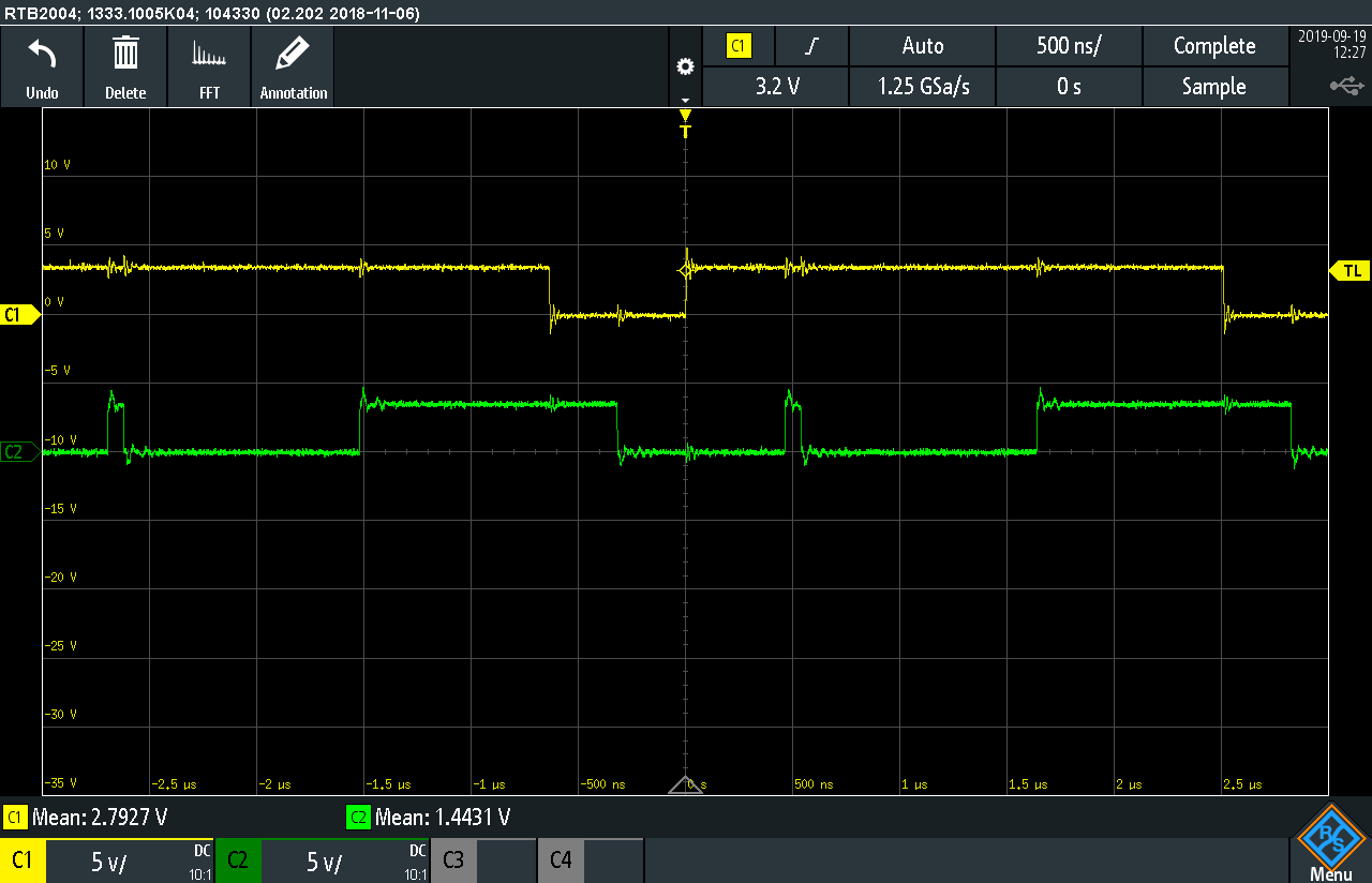
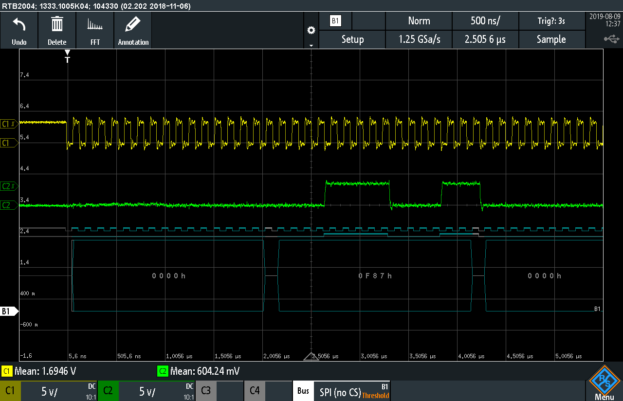
Taken a look into the bare SPI communication it looks as follows:
TIME1 is OK, value is 0x29A:

TIME1 is NOT OK, value is 0xF87:
This happens approximately 1 out of 10 times. TIME1 then always has 0x0Fxx, where as 0x02xx would bring the value to a reasonable area.
It seems to me, that the second byte of TIME1 (bits 8 - 11) are corrupted by the TDC somehow. I have no idea how to explain that otherwise. Or am I missing a point?
Cheers Benjo
EDIT:
I found cases where TIME1 has not 0x0Fxx but 0x10XX:

I also checked the 16MHz clock of the TDC and it looks fine. No glitches or noise on the clock.
Cheers Benjo