This thread has been locked.

If you have a related question, please click the "Ask a related question" button in the top right corner. The newly created question will be automatically linked to this question.

AWR1642: How to understand Ripple Specifications in AWR1642 datasheet

Part Number: AWR1642

Hello team,

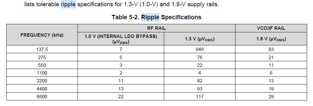
Customer want to test the ripple on AWR1642 power rail, but he found below table from datasheet. Could you please help to calirify the test senario of this table? And how to make a conclusion that power tree performance is good enough for AWR1642?

Is it same requirement for no-load and full load? But the AWR1642 is also work in pulse mode. How to measure the performance of power rail?

Thansk,

wesley

  • Hello Wesley,

    Below is the more detailed description of the values in the table. Let me know if it helps.

    The 1.3V (1.0V) and 1.8V power supply ripple specifications mentioned in Table  are defined to meet a

    target spur level of –105dBc (RF Pin = –15dBm) at the RX. The spur and ripple levels have a dB to dB

    relationship, for example, a 1dB increase in supply ripple leads to a ~1dB increase in spur level. Values

    quoted are rms levels for a sinusoidal input applied at the specified frequency.

    Regards,

    Vivek

  • Hello Vivek,

    One more question, how did customer measure these parameter on their board. To confirm that their power solution is good enough for the radar?

    Can you please provide the measure method for oscilloscope to measure it?

    Thanks,

    Wesley

  • Hello Wesley,

    This cannot me measured using oscilloscope since the noise levels of a scope prevent such low level noise measurements. They could use a spectrum analyzer to measure the levels. But it could be tricky since care needs to be taken to avoid any direct coupling path from the PMIC to the probe (via radiation).

    Regards,
    vivek