This thread has been locked.

If you have a related question, please click the "Ask a related question" button in the top right corner. The newly created question will be automatically linked to this question.

FDC2214: FDC2214RGHT

Part Number: FDC2214

Hi

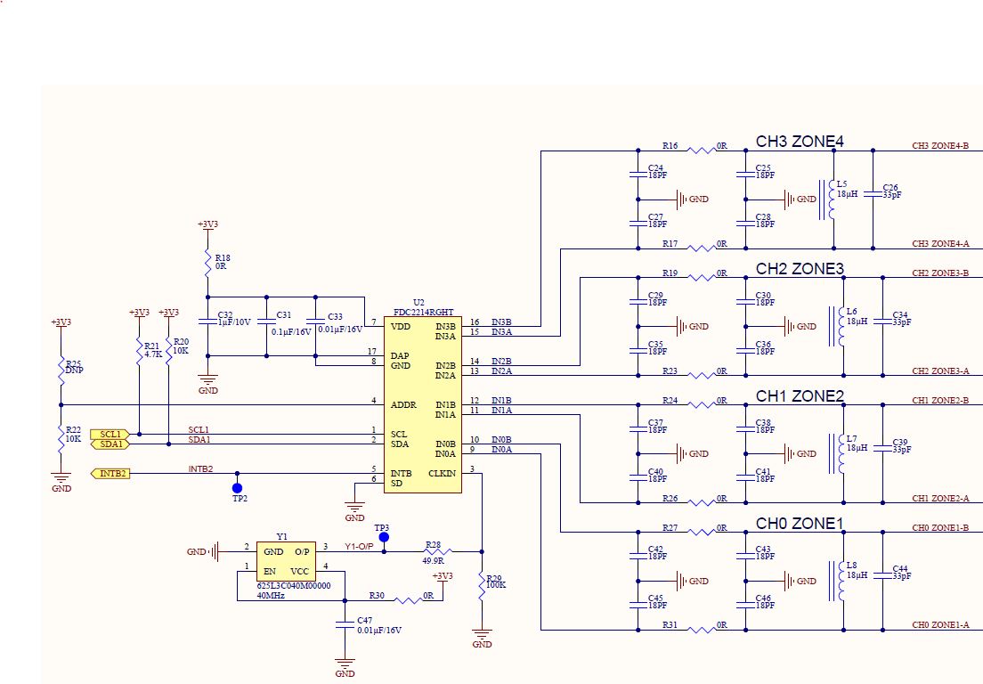
We have been using FDC2214 for capacitance sensing application. In our application, the sensor capacitance can change from 500pF to 3nF during measurement. We have 18uH and 33pF which forms the tank circuit on PCBA and the sensor is connected in differential configuration. Please clarify the below queries:

  1. We came across the application report SNOA950 - setting drive configuration in LDC. Is the "peak sensor oscillation voltage" equation 2, applicable to FDC2214 also?
  2. Can we configure Automatic amplitude setting in FDC2214? Will this mode dynamically sets the amplitude within the range 1.2 - 1.8V during operation?

Thanks

Vishnu

  • Hello Vishnu,

    Yes, the sensor drive configuration application note is also applicable to the FDC2214. It's not possible to use the automatic amplitude setting with the FDC2214; however, this mode can introduce offsets into the digital output, so we only recommend using it for testing anyway.

    Best Regards,

  • Hello Kristin

    Thanks for the reply.

    We have observed the following on testing our capacitance sensor with the TI EVM board and our PCBA :

    1. The amplitude of oscillation in one of the channels was found to be 2.5V, whereas it was 1.8V in the other three. We have configured the same IDrive value (306uA) in all the channels.
    2. On testing the sensor with our PCBA, for the same settings (Idrive, Rcount, Settlecount) as in TI EVM, the amplitude of oscillation was 7V in one of the channels and it was within 1.8V in the other three. Also, the tank circuit is the same as in EVM.

    Could you please share your thoughts on this?

    Thanks

    Vishnu

  • Hello Vishnu,

    It's very concerning that the oscillation amplitude was so high on one of the channels. Could you share your schematic? It's extremely surprising to me that the FDC2214 (which is a 3.3V part) could generate 7V on one of the channels. 

    Best Regards,

  • Hello,

    I haven't heard from you in a while, so I'm assuming you were able to resolve your issue. If this is not the case please feel free to reply to this thread or post a new question.

    Best Regards,

  • Hi Kristin

    Sorry for the delayed response.

    Please find the attached schematic.

    We have two no.s of the below circuit on board, for interfacing 8 capacitors in differential configuration.

    Thanks

    Vishnu

  • Hi Vishnu,

    Your schematic looks good to me. It may not be possible to find a single drive current to keep the oscillation amplitude amplitude within the ideal range for the full range of your sensor capacitance (though I strongly recommend this if possible). You may need to change your drive current as your sensor capacitance changes. Below 1.2V your SNR will reduce, and above 1.8V the ESD diodes can turn on and reduce your measurement accuracy.

    Best Regards,

  • Hi Kristin

    Thanks for the reply.

    1. In the application report SNOA950, equation 2 shows that peak oscillation voltage depends on Idrive, L and C values. So for higher L and lower C values, won't the voltage exceed 3.3V?

    2.Is the internal resonant circuit driver a constant current source?

    3. Also, in the schematics i have shared, the 40MHz oscillator output is shared between the 2 FDC2214 ICs, is it advisable to do so? Is there any particular specifications such as jitter, for the clock ? 

    Regards

    Vishnu

  • Hi Vishnu,

    For the same drive current, high L and lower C values would result in a higher Rp value and a higher oscillation amplitude. However the oscillation amplitude should never exceed 3.6V because the current source is referenced to an internal node, and the FDC2214's maximum recommended Vdd is 3.6V.

    The driver is a constant current source that alternates being applied to INxA and INxB. 

    If the FDC2214 devices are not spaced very far apart on the board (and depending on the maximum capacitive load of your oscillator), you may be able to share an oscillator. The most important oscillator specs for the FDC2214's accuracy are very low drift over temperature and low jitter. The oscillator used on the FDC2214EVM is a good option.

    Best Regards,

  • Hi Kristin

    The below waveform shows the oscillation output when the sensor value is around 500pF. 

  • Hi Vishnu,

    Are you measuring INxA and INxB with a differential probe? When measuring INxA with respect to the FDC2214's local ground, you should see a half-rectified sin wave. The amplitude of this waveform should not exceed 1.8V when the drive current is set correctly. The peak-to-peak voltage across INxA and INxB will be larger. The maximum peak-to-peak voltage you could see if the Idrive was set way too high and the oscillation amplitude railed would be ~7V.

    Also please note that I will be on vacation next week and my responses will be delayed until I return.

    Best Regards,

  • Hi Kristin

    I was using an isolated oscilloscope -  floating measurement was done across INxA and INxB.

    Please see the below image - when probed across INxA and GND.

    The peak value reaches around 2.1V initially and settles to 1.64V

  • Hi Vishnu,

    My apologies for the delayed reply; I was on vacation all of last week.

    The oscillation amplitude looks good now.

    Best Regards,

  • Hello Kristin,

    I tried to test the IC with fixed capacitor values - maximum 10nF. I connected a toggle switch in series with 10nF on 1 channel and connected fixed values on all other. Please see the below plot of capacitance vs no. of samples in the channel on which i have connected switch.

    I have observed the below overshoot, which was not repeatable . Also, i could find at times the capacitance drops to zero at irregular intervals after the transition to 10nF (i will share an image of it).  Does this occur due to the instability of the tank circuit? Is there any upper limit on the capacitance that can be connected for a particular inductor value or drive current? i could find from the datasheet that the IC can sense upto 250nF, with an inductor value of 1mH.

    I'm not sure of it as both these cases were not regular or repeatable.

    Thanks

    Vishnu

  • Hello Vishnu,

    There is definitely an upper limit to the sensor capacitance for a given inductor value. I recommend reading section 1.2 of LDC Sensor Design. Though the application note is primarily useful for inductive sensing, section 1.2 describes Rp of an LC tank sensor, which is used by both the FDC2xxx devices and the LDC devices. As the capacitance of your sensor changes, the Rp value will also change, which changes the oscillation amplitude of your sensor. I suggest measuring the oscillation amplitude at both the minimum and maximum sensor capacitances to verify that it is within the optimal range.

    These spikes can sometimes occur if the oscillation amplitude is out of range. Sometimes spikes like the one shown in your second image can be caused by EMI, so I recommend using the filter capacitors shown in the FDC2214EVM schematic.

    Best Regards,