This thread has been locked.

If you have a related question, please click the "Ask a related question" button in the top right corner. The newly created question will be automatically linked to this question.

LDC2114: LDC2114 Issue

Part Number: LDC2114
Other Parts Discussed in Thread: LDCCOILEVM, LDC1614

Hi Sir,

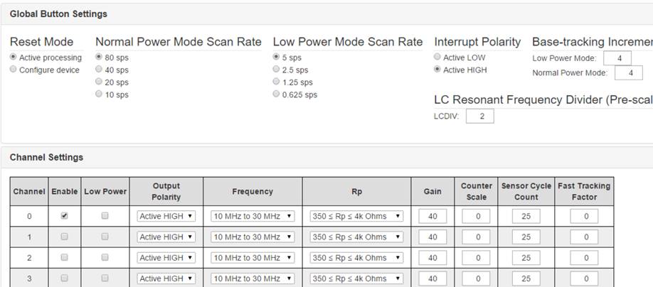
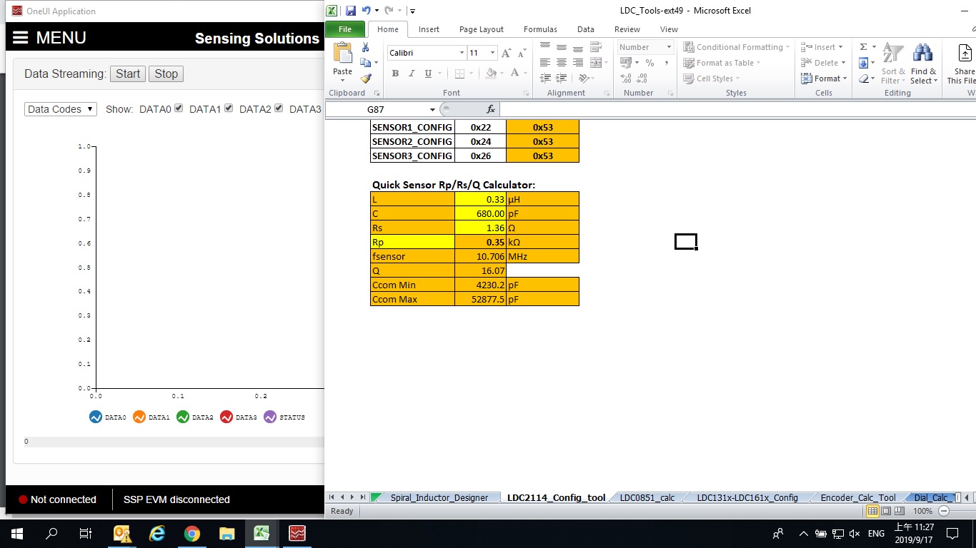
We uses LDC2114 EVM and setup: L=15uH (MLZ2012M150W), C=15pF (NPO)

These values will:

fsensor=10MHzèok

Q=21.3èok

Rp=612Kè over spec (350~10K ohm)

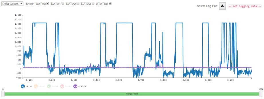
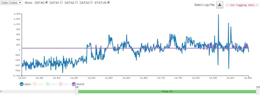
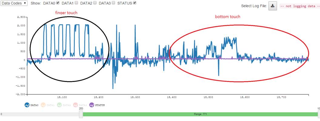
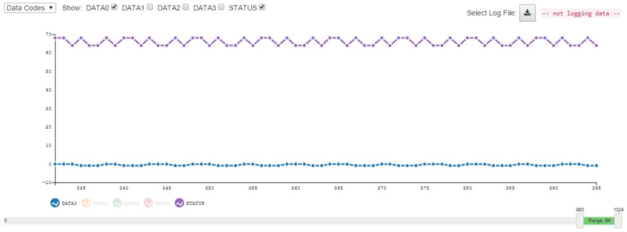
But it looks not working on EVM, would you pls advise how we can let EVM working formal?

Thanks, Ian.


  • Hello Ian,

    That sensor Rp value is far too high for the LDC2114 to effectively drive. To solve this, your customer can add series resistance or increase the capacitance value until the Rp value is below 10kohms.

    Best Regards,

  • Hub jones,

    Do you have suggest L. C value for trying? It’s hard to meet three conditions, thanks.

    Thanks, Ian.

  • Hi Ian,

    The values used in the calculations above don't match the actual L and Rs values of Coil N in the LDCCOILEVM. You can find the actual values in this document: http://www.ti.com/lit/ug/snou136/snou136.pdf. That coil's inductance is only ~0.25uH, depending on the sensor frequency. With a 15pF sensor capacitor the resonant frequency is roughly 80MHz. The maximum sensor frequency that the LDC2114 can drive is 30MHz. Try using 150pF or greater instead of 15pF for the sensor capacitor.

    Best Regards,

  • Hi Sir,

    We already follow this document, but can’t find suitable L & C to meet LDC2114 conditions. (you can calculate again. )

    Could you help provide suitable parameter to me?

    Thanks, Ian.

  • Hi Ian,

    I highly recommend using the LDC Tools Excel Calculator to find LC values that work. The Contents tab has a quick sensor Rp/Rs/Q calculator that should help. There is a huge range of both L and C values that will work with the LDC2114.

    If your customer would like to use coil N, they do not need to add a series inductor with the LDC2114. That footprint is available for other LDC devices that cannot drive very small coils. One option is to short L_N and add a ~700pF capacitor. 

    Best Regards,

  • Hi Jones,

    Thanks for your help, It looks better~

    LDCCOILEVM (N-Coil) with L=0uH & C=680pF

    These values will change:

    fsensor=12.31MHzèok

    Q=0.8èover spec (5~30)

    Rp=510è ok (350~10K ohm)


    But for my customer's keyboard coil, seems still need to fine tune.

    Customer's keyboard (E-Coil, 0.26uF) with L=0uH & C=680pF

    These values will change:

    fsensor=11.97MHzèok

    Q=0.9 - over spec (5~30)

    Rp=539 - ok (350~10K ohm)


    Remove metal sheet, use finger touch is fine but with bottom will not good, would you pls advise what we can fine tune?

    Thanks, Ian.


  • Hi Ian,

    Can you clarify how you found the Q value to be less than 1? By my calculations with the values you shared, the Q value should be close to 30. I used the LDC Tools Calculator for this.

    Please also verify that the INx waveforms look like Figure 7 in this document: http://www.ti.com/lit/an/snoa963/snoa963.pdf

    Please note that the INx pins are very sensitive to parasitic capacitances from passive probes, so we recommend isolating the probe with a 1kohm resistor.

    Best Regards,

  • Thanks for information, Q close to 30 is correct. EVM can work fine with LDCCOILEVM (N-Coil).

    Now, we change to using customer's coil and set as below,


    It works fine when using finger touch, pls see left black block as below picture,

    But when we have bottom upon coil, it works bad as right red block in above picture,

    Pls advise how can we fine tune to let it work fine using bottom?

    Thanks, Ian.

  • Hi Jones,

    Pls advise if possible you can help us to fine tune it with bottom?

    The end customer is H customer, application is gaming keyboard, H push us hard and we need your help.

    Thanks, Ian.

  • Hi Ian,

    It looks like the coil's Rp is too low. The calculator tool shows that the Rp value is 350 ohms, which is the minimum Rp value that the LDC2114 can effectively drive. The calculator tool can sometimes differ from the physical values, so it's possible that the sensor's Rp is too low. Although the bottom plate looks like it is recessed enough away from the coils, it's possible that it is slightly reducing the Rp value, which makes it even harder for the LDC2114 to drive effectively.

    I do recommend measuring the actual Rp value of the customer's coil using one of these methods.

    If the Rp value is too low, a quick fix is to reduce the sensor capacitance value. Also please note that parasitic PCB capacitance and the input capacitance on CINx (typically 15pF) will also affect both the sensor oscillation frequency and the Rp value. This additional capacitance would further reduce Rp.

    Best Regards,

  • Hi Jones,

    We increase Rp but look like not have huge improve.

    If possible you can help tuning it for us with real bottom/PCB?

    Thanks, Ian.  

  • Hi Ian,

    Can you clarify what kind of help your customer needs? I am not able to test your customer's board myself, if that's what you're asking.

    Best Regards,

  • Hi Jones,

    I follow your comments increase Rp to 740 ohms, looks similar result, it's not working with bottom touch.

    Do you have others suggest? 

    LDC1614 is suitable kind of application? Or FDC will better to use this bottom application?

    Thanks, Ian.

  • Hi Ian,

    The LDC2114 would be the most suitable device for this application. The LDC1614 would require a detection algorithm to be implemented on an MCU, and it cannot drive sensors with Rp values below 1kohm. 

    Best Regards,