This thread has been locked.

If you have a related question, please click the "Ask a related question" button in the top right corner. The newly created question will be automatically linked to this question.

OPT3101: how to choose the external capacitor Cpd value to match the photodiode?

Part Number: OPT3101

Hello

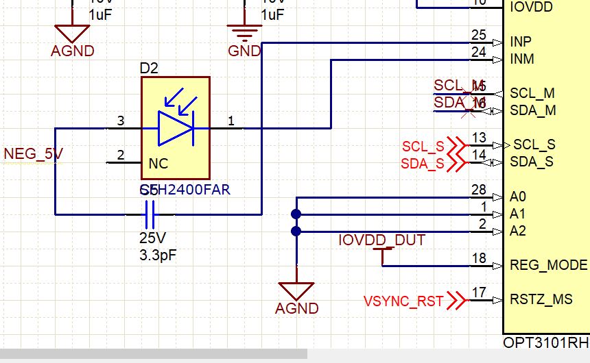
I use photodiode SFH2700 FA and use a capacitor Cpd=5.8pF as matching capacitor on my design, is that ok?  on the SFH2700FA datasheet, there is a curve for capacitance vs VR voltage. but how can I choose the matching Cpd value based on the curve?

thanks

  • Hi,

    OPT3101 will bias the PD at 1V so you want to pick the capacitance at 1V. Also since you are designing a board I wanted to make sure you are following all the guidelines in our system design doc online. Can you please confirm?

    When you finish schematic/layout please send to me before you build and I can also do a quick check as well for you.

    Could you also give me some background on your application and use-case for this project?

    Best,

    Alex

  • for the photodiode SFH2700FA, the capacitance at 1V is 3pF, but I put 5.8pF matching capacitor on my design,  is that a big problem? what is the consequence it will cause?

    my project is a warehouse antomation system, OPT3101 is used to detect the obstacle on a moving machine. now is in early development stage.

    I attach the schematic and PCB file ( altium ) but not sure you can see them. if not, pls give me your email address and I will send them to you ASAP.

    currently my board can read/write data, but seems the data we read out is not correct.

    so I connect my board to the TI evaluation board. and run LATTE software to control it. the latte can run and read out data, but the distance and amplitude info still not correct.

    so my question is: pls help check if the LED emmiter or photodiode is not correct , or if the matching capacitor cause problem. ( should be 3pF but I put 5.8pF).  

    pls help , thankshttps://e2e.ti.com/cfs-file/__key/communityserver-discussions-components-files/1023/TI-OPT3101-drawing.7z

  • Hi,

    Is this the same project as this post? https://e2e.ti.com/support/sensors/f/1023/t/837260#pi320995=2

    In the above thread they were asking about getting accurate data which requires calibration, but we would want to resolve the design first before proceeding to calibration.

    Yes mismatched matching cap could cause problems. Have you already built the board? Are you able to swap out the cap?

    I can review this schematic and get back by next week with my suggestions on the overall design.

    Best,

    Alex

  • yes. it is the same project 

    pls review the schematic and layout and I will swap the matching capacitor to test too

  • Hi,

    For cap and beads please ensure these conform to the impedance requirement at 10MHz.

    Additionally the layout does not seem to follow our guidelines in terms of the PD and LED being so far from the OPT3101. I have not seen a design where this large a loop was working. So to be clear we definitely do not recommend a layout like this. Biggest issue I see will be sensitivity to outside objects along the loop axis. However, we can to some checking to see if the design is useable. Can you please provide the raw crosstalk amplitude? This is the amplitude when the photodiode is masked (no light from LED able to reach it) and no calibration correction is done for crosstalk. Please let me know this number and we can see how it looks.

    See step 4 here for an example of masking on the EVM https://e2e.ti.com/support/sensors/f/1023/t/727462

    For info on both points above please see our system design doc listed here: https://e2e.ti.com/support/sensors/f/1023/p/815766/3019009#3019009

    Best,

    Alex

  • thanks. our layout really is not good. we will use your suggestion to design the board. thanks very much

  • Hi,

    Okay. If you like, please send me your layout and design before building the boards and I will check them to make sure if you do a redesign it will perform well. Also we have an update to the design guidelines to further reduce crosstalk which using a -5V as PD ground. Please refer to the screenshots below.

    Also what was the crosstalk level measured in your current PCB design?

    Best,

    Alex