Dear Sir,
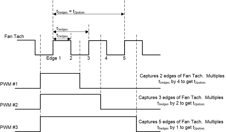
From LM63 datasheet show "Note: If the PWM Clock is 360 kHz, mode 00 is used regardless of the setting of these two bits." it's mean register "4A" bit 3 set to "0" the Tachometer Mode can't use "10" and "11" mode? What is the working principle of Smart-tach mode? If my fan PWM frequency is 25kHz, how can I do the Lookup table to control the fan speed?
Best regards
Sam