This thread has been locked.

If you have a related question, please click the "Ask a related question" button in the top right corner. The newly created question will be automatically linked to this question.

AWR1243: How to communicate with AWR1243 using MCU

Part Number: AWR1243
Other Parts Discussed in Thread: MSP430F5529, ,

Hi Team,

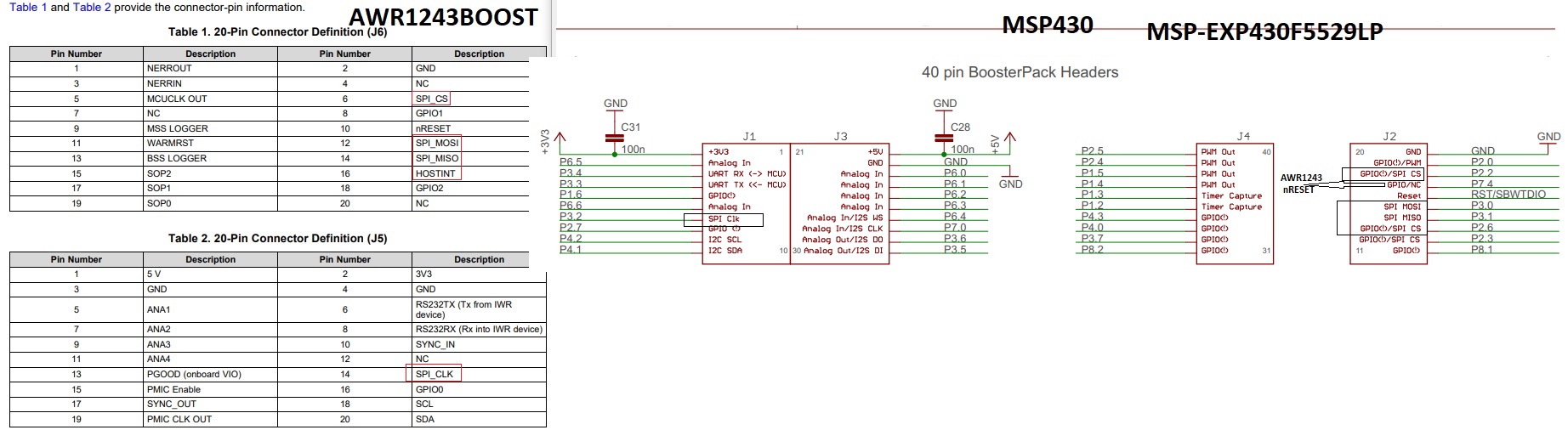
Customer has AWR1243BOOST + MSP430F5529. Both have LaunchPad. Customer wants to use the MSP430 to control the AWR1243 via the SPI interface. He also saw mmwavelink.example in DFP. Customer would like to know how to remove the routine to MSP430?

Thanks.

  • Hi Annie,

    Connect AWR1243 with External MCU


    AWR1243 device requires at least these hardware lines to be connected with external MCU for control interface over SPI.

    1. SPI: MOSI, MISO, CS, CLK.
      1. AWR1243 acts as SPI slave so Ext. MCU needs to drive these SPI lines as Master where it provides the SPI clock to AWR1243 when it requires sending data.
    2. HOSTINT: Host interrupt line
      1. As SPI slave AWR1243 uses this line to notify External MCU to send any data from it.
      2. This line will be connected to one of GPIO to ext. MCU as input.
    3. nRESET:
      1. This is reset line for AWR1243 which ext. MCU needs to take high to power on the sensor.
      2. This line will be same RESET line on MSP Launchpad. So user needs to connect nReset (AWR1243BOOS J6:10) to MSP Launchpad (GPIO J2: P7.4) GPIO to control.
    4. SOP line:
      1. These lines can be control via AWR1243BOOST SOP Jumpers to make sensor in functional mode before taking nReset high by MCU.


    Please refer the AWR1243BOOST and MSP Launchpad datasheet to find these lines on the board.

    Now in the software implementation-

    mmWaveLink is a platform independent library which has all the AWR1243 control API and protocol implemented in it. It requires few of callback to be implemented at the application to access platform HW (SPI, HostINT, nReset). Application needs to provide and implement these callback functions and invoke mmWaveLink ‘rlDevicePowerOn’ function.

        clientCtx.comIfCb.rlComIfOpen = /* Initialize SPI as Master (refer AWR1243 datasheet section 5.9.4 for SPI specification) and set P2.2 as input GPIO */

       clientCtx.comIfCb.rlComIfClose = /* deinit SPI driver */

        clientCtx.comIfCb.rlComIfRead = /* function to read the SPI data, refer mmWaveLink to find the this callback function definition */

        clientCtx.comIfCb.rlComIfWrite = /* function to write data to SPI, refer mmWaveLink to find the this callback function definition */


       clientCtx.devCtrlCb.rlDeviceDisable =/* callback function to power off AWR1243; De-Assert Reset GPIO*/

        clientCtx.devCtrlCb.rlDeviceEnable = /* callback function to power ON AWR1243; Assert Reset GPIO line*/

        clientCtx.devCtrlCb.rlDeviceMaskHostIrq = /* function to mask the HOSTINT GPIO interrupt */

        clientCtx.devCtrlCb.rlDeviceUnMaskHostIrq = /* function to unmask the HOSTINT GPIO interrupt */

        clientCtx.devCtrlCb.rlRegisterInterruptHandler = app_RegisterInterruptHandler ; /* Register the HOSTINT with the GPIO interrupt */

        clientCtx.devCtrlCb.rlDeviceWaitIrqStatus = /* To check HostINT GPIO status to low/high */


    RL_P_EVENT_HANDLER g_RlInterruptFunc;

    char gDeviceIndex = 0;

    rlInt32_t app_RegisterInterruptHandler(rlUInt8_t deviceIndex, RL_P_EVENT_HANDLER pHandler, void* pValue)

    {

       g_RlInterruptFunc = pHandler;

       return 0;

    }

    /* GPIO interrupt handler for HotINT*/

    void gpioIsr(gioPORT_t *port, uint32 bit)

    {

                 g_RlInterruptFunc(0, &gDeviceIndex);

    }


    Implement semaphore and mutex callbacks as OS supports.

    And please refer mmwavelink.h where each of callback functions is added with the proper information for implementation.


    Refer this similar thread-

    https://e2e.ti.com/support/sensors/f/1023/p/799855/2982538#2982538


    Regards,

    Jitendra