This thread has been locked.

If you have a related question, please click the "Ask a related question" button in the top right corner. The newly created question will be automatically linked to this question.

TDC1000-TDC7200EVM: Switching circuit problem for water flow meter

Part Number: TDC1000-TDC7200EVM

Hello,

I have problem with getting result obtained in "UltrasonicSensingfor WaterFlowMetersand HeatMeters"  (Application Report SNIA020).

I use transducers US0019 (by audiowell with Resonant impedance ≤220Ω; frequency 980±30KHz; Static capacitance 550±20%pF), TDC1000, TDC7200 and switching circuit

I used values from document above and made a lot of sweeps of values and my deltaTOF is still floating in range -500/+500ps in best case. No metter of temperature within minutes.

Do you have some guides of how to pick out resistors values and RX parrarel capacitor to make more preciese measurements.

Looking forward for your reply.

Best Regards,

  • Krzysztof,

    Please describe your setup more in detail. I would like to know details like the type of pipe used in the flow metering, is the transducer placed in intrusively or clamped.

    Also I assume you are using the TDC1000-TDC7200 EVM.

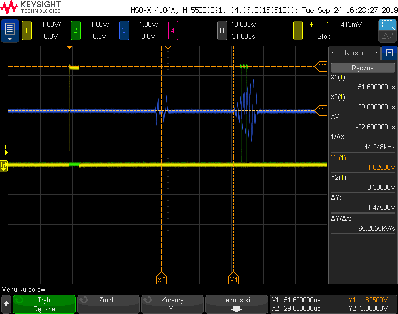
    Please send me plots of the START, STOP & COMPIN Pin.

  • Hi Bharat,

    I have two setups on which the results are almost same.

    First setup consist of TDC1000-TDC7200 EVM + Switching board and custom tube with US0019 by Audiowell.

    Second setup consist of MCU+TDC1000+TDC7200+Switching circuit on single PCB + same custom tube.

    Transducers are placed intrusively, faceing each other without any mirrors inside tube. Distance between transducers are nearly 80mm, TOFs at no flow are ~55us.

    I'm using 8-10 TX, 3Stops, 3rd level of PGA and 4th level of THS;

    Plots You asked for below.

    Edit: As you can see on COMPIN signal there is peak @~29us after first TX, I can see it on both EVM and my PCB. Do you know what could be the origin of this peak.

    Best regards.

  • Dear Bharat,

    My recent configuration is custom PCB and custom pipe.

    I made some changes in switching circuit (higher resistance in series of TX, lower resistance in parrarel to RX and TX) but still don't know what is purpose of capacitance connected to pin 6 of TS3A44159PWR and I dont see changes when changing to 150pF or 600pF. Could you please expain the purpose?

    Im using TDC7200 averaging with 64 samples, 8MHz clock is always powered on now, I added 22nF capacitor to VCOM which improved results pretty well.

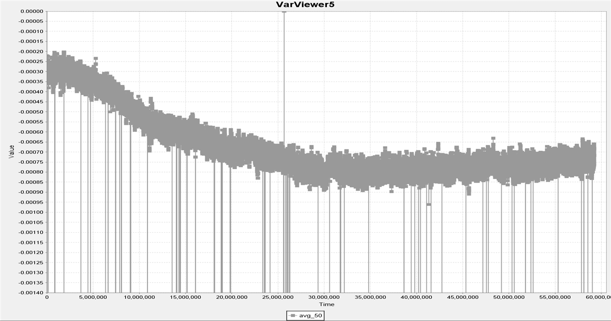
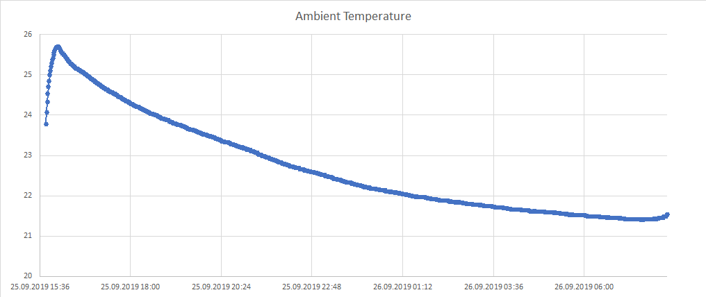
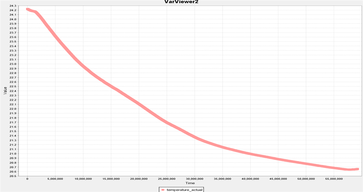
    I prepered test yeasterday which took 16hours. I was measuring and collecting dTOF and water temperature with TDC1000+TDC7200 and ambient temperature for reference. Here are my results (all times in miliseconds):

    1. Delta TOF, started with mean value -300ps. After almost 9hours stabilized at -800ps mean value. (Peaks in results are bug from collecting software not mcu firmware)


    2. Ambient temperature, and temperature from TOF. Both are similar but doesnt have shape exactly same as dTOF.

    3. After opening water flow at end of this test and closing the flow level of approx -800ps remained.

    4. Then I heated the water to 30degC, but still -800ps remained, but then when the temperaure was going slowly to 20degC level of dTOF was going back to starting point -300ps.

    5. I was heating both PCB and pipe when it's on -300ps level and almost nothing happens (changes smaller than 50ps of mean level)

    What could be the reason of this change from -300ps to -800ps?

  • Dear Bharat,

    Do You have any idea what could be wrong with setup?

    Best Regards.

  • Krzysztof,

    I am reviewing your info and will respond by next Tuesday.

  • Krzysztof,

    Sorry for the delay, I am still working on your issue to check what could be the reasons and I will get back positively before this Wednesday.

  • Krzysztof,

    The signal that you see @ 29uS should be from the walls of the tube right between the 2 transducers or disturbances in the water/liquid.

    In order to avoid wrong readings due to such noise we can increase the number of Rx signal pulses to 4/5 (STOP pulses).

  • Krzysztof,

    Please note that the 300ps connected at the pin 6 just mirrors the actual 300ps connected at the Rx path. This 300ps connected at the Rx path helps in blocking DC component to the device. So you wont see any change when you try to change its value.

    In your entire experiment what was the actual expected ToF. ? Looks like the ToF value decreased to 800ps from 300ps. 

    In understand the maximum experiments you have done with this device, In case you require a very high precision flow metering with good resolution, we recommend that you use the MSP430FR6047 device:

    http://www.ti.com/tool/MSP-ULTRASONIC-DESIGN-CENTER

  • Dear Bharat,

    Thank you for your response.

    ToF is something around 52us. On the plot I posted it was delta TOF at zero-flow (300ps to 800ps). 

    Now I made some workaround for the problem:

    • For "regular" measurement I make just 7 TX pulses and I measure 4 & 5 Stop for best accuracy,
    • Once per X minutes I make "calibration" mesurement. It consist of 16TX pulses + extended autozero period to measure the signal in the further part of RX signal. As far as I observed further part of RX signal is more stable in case of more TX pulses. With calibrated measurement there is no temperature based drift and I'm able to zero regular measurement.

    Do You have any conclusions?

    Best regards.

  • Krzysztof,

    Whenever there is zero-flow in the pipe any disturbance in the water/gas in the pipe can cause the device to report ToF such as the once's you see now.

    Hence we recommend the user to modify the PGA gain, Number of Tx & Rx pulses such that they receive stable readings.

    I understand that you get stable zero measurement result when you measure the signal at the further part of Rx signal. If this is the case then your initial measurements from Rx has some noise/ringing associated with it and that could be either from the wall sides/burst energy of the Tx signal that the Rx senses.

  • Krysztof,

    Additionally, mismatch between transducers will cause the delta TOF to drift away from zero in a zero flow condition. I am linking two application notes that address this issue and provide some examples of analog interface circuits that can mitigate this problem. One is based mostly on gas flow sensing, but both have pertinent information on this topic.