This thread has been locked.

If you have a related question, please click the "Ask a related question" button in the top right corner. The newly created question will be automatically linked to this question.

IWR6843ISK: MIMO BPM antenna patterns

Part Number: IWR6843ISK

Hi TI,

Do you have any diagrams of TX antennas (e.g. TX0 and TX2) in first and second iteration of BPM (when transmitting both at once)? I can imagine the first case where TX0 and TX2 phases are equal.

However, I'm curious about opposite phases of transmitted signal as it could results in something like extreme case of beamforming.

Thank you for your answer, Lukas

  • Hi User,

    I've asked an expert to look into this and we should have an answer for you in the next few days.


    Cheers,

    Akash

  • Hi Lukas,

    There are a couple of ways in which this can be understood.  One way is the following

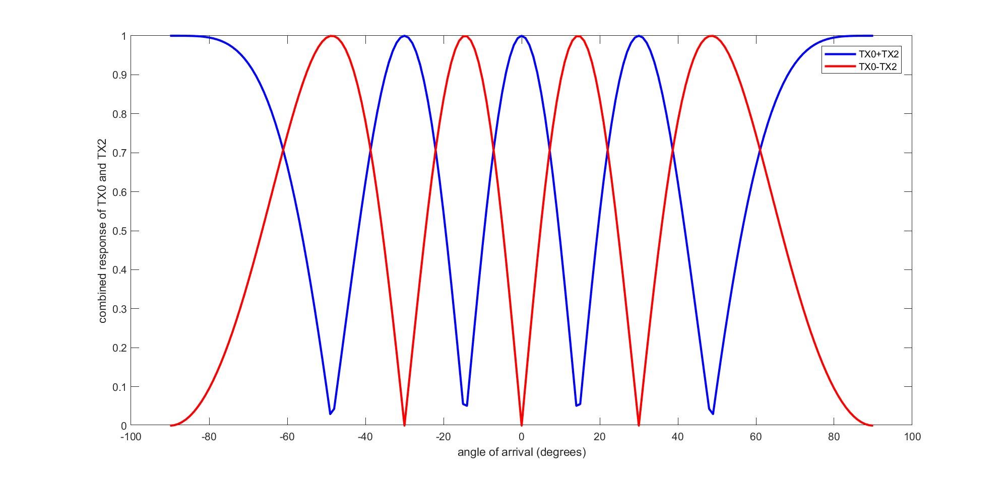
    1. When the two transmitters transmit in phase => they strongly illuminate the center of the Field of View (FoV). However, there will be nulls created at other angles. For example when the two transmitters are one wavelength apart and transmit in phase : there will be nulls at  +/-30 degrees.

    2. Next, when the two transmitters transmit with opposite phases : their signals cancel at the center of the FoV. However, they will now strongly illuminate at angles of  +/-30 degrees.

    3. So cumulatively both the transmissions together (TX0+TX2, TX0-TX2) illuminate the whole scene.

    Sandeep

  • Thank you Sandeep, this sound sensible.

    However, in case of TDM, there are (almost) the same object with (almost) same energy in both iterations. I can't imagine this in case of BPM, as there will be varying energy of objects between first (S1 and S2 both 0 degree phase) and second transmission (where S2 has 180 degrees phase). Then the calculations as stated here (http://www.ti.com/lit/an/swra554a/swra554a.pdf)

    S1=(Sa+Sb)/2

    S2=(Sa-Sb)/2

    can't simply work I believe. Or at least I can't imagine the results. Am I missing something?

    Thank you, Lukas

  • Hi Lukas,

    A different way to understand this is to think of BPM as a super-position of the TDM use-case.

    Consider a single RX antenna that is listening to the transmissions from TX0 and TX2. 

    1. When TX0 is transmitting, let the received signal be S1.

    2. When TX2 is transmitting, let the receive signal be S2. Likewise if TX2 is transmitting with a 180 degrees phase , the received signal would be -S2

    By super-position (the EM waves add linearly), the received signal when both TX0 and TX1 are transmitting in phase will be Sa= S1+S2 (just the sum of the individual transmissions). Likewise when TX0 is transmitting as is, and TX2 has a 180 degrees phase imparted - the received signal will be Sb-S1-S2. 

    Thus with knowledge of Sa and Sb, the signals S1 and S2 can be calculated. Note that : in this description I ignore the object velocity, otherwise there is a velocity induced phase correction required.

    BTW,  I am attaching  a plot of the combined antenna response (TX0+TX2, TX0-TX2), when TX0 and TX2 are 2*lambda apart (as in the 6843 ISK). You can see that the two responses nicely complement each other (one has peaks , in places where the other has nulls)

    Sandeep

  • This view makes it clear. Thank you!

    I think you still prefer TDM in demos, is there any reason fro this?

    Lukas

  • Thanks Lukas

    I don't think the bias is intentional. Historically, we did implement the TDM first (and so most of the initial demo's are  in TDM).