This thread has been locked.

If you have a related question, please click the "Ask a related question" button in the top right corner. The newly created question will be automatically linked to this question.

PGA460-Q1: BOOSTXL-PGA460 GUI Reading and actual distance mismatch

Part Number: PGA460-Q1
Other Parts Discussed in Thread: BOOSTXL-PGA460, PGA460

Dear Members,

I have been using BOOSTXL-PGA460 EVM in bi-static mode for distance measurement. I am using audiowell transducers having center frequency of 58.6KHz. The transducer specifications are similar to Murata MA58MF14-7N transducer. My test setup is shown below:

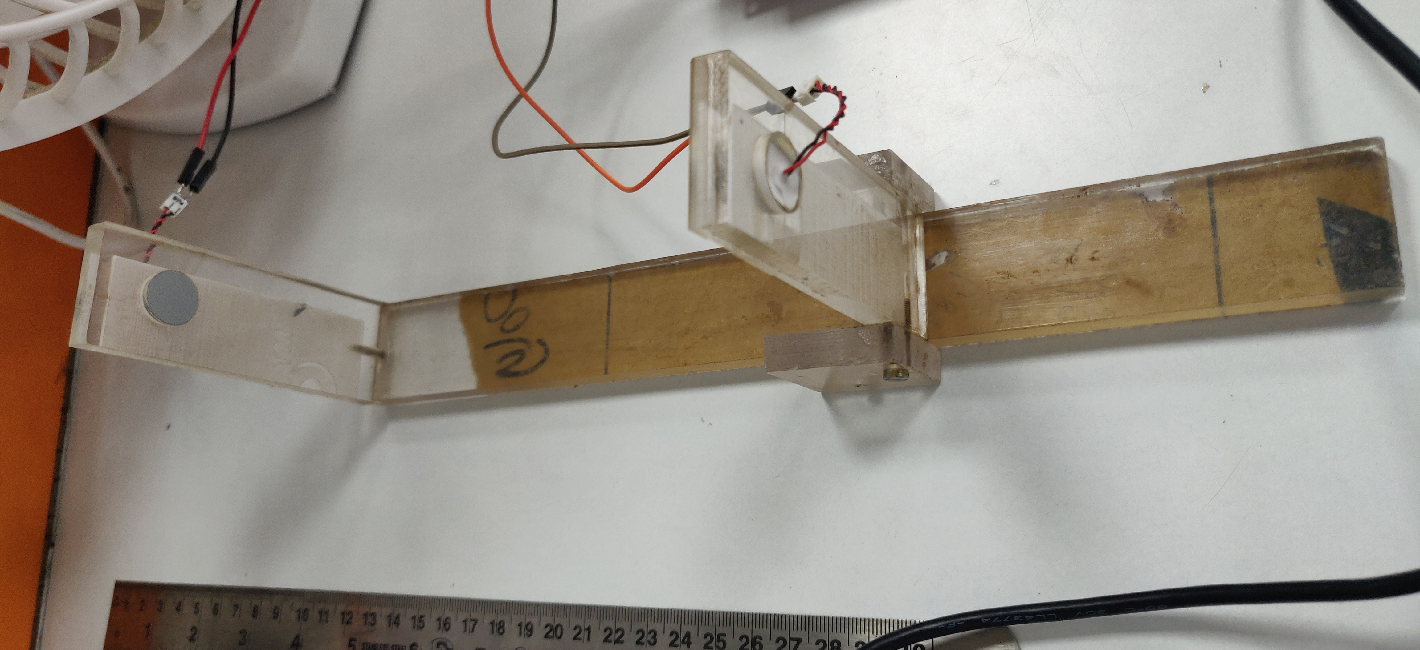
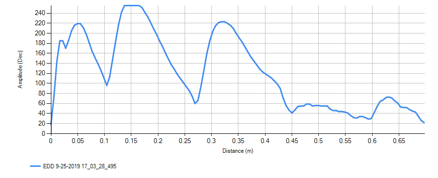
Distance between transducers has been kept at 166mm. But i am getting a reading of around 120mm on EDD in GUI. Please find attached below image of EDD:

Damping resistor used is 10k and a tuning capacitor of 680pF is used. 

Register settings used are in the attached text file.

;GRID_USER_MEMSPACE
00 (USER_DATA1),00
01 (USER_DATA2),00
02 (USER_DATA3),00
03 (USER_DATA4),00
04 (USER_DATA5),00
05 (USER_DATA6),00
06 (USER_DATA7),00
07 (USER_DATA8),00
08 (USER_DATA9),00
09 (USER_DATA10),00
0A (USER_DATA11),00
0B (USER_DATA12),00
0C (USER_DATA13),00
0D (USER_DATA14),00
0E (USER_DATA15),00
0F (USER_DATA16),00
10 (USER_DATA17),00
11 (USER_DATA18),00
12 (USER_DATA19),00
13 (USER_DATA20),00
14 (TVGAIN0),44
15 (TVGAIN1),34
16 (TVGAIN2),44
17 (TVGAIN3),65
18 (TVGAIN4),B7
19 (TVGAIN5),ED
1A (TVGAIN6),C4
1B (INIT_GAIN),18
1C (FREQUENCY),8F
1D (DEADTIME),10
1E (PULSE_P1),05
1F (PULSE_P2),14
20 (CURR_LIM_P1),07
21 (CURR_LIM_P2),FF
22 (REC_LENGTH),07
23 (FREQ_DIAG),11
24 (SAT_FDIAG_TH),22
25 (FVOLT_DEC),69
26 (DECPL_TEMP),CF
27 (DSP_SCALE),00
28 (TEMP_TRIM),00
29 (P1_GAIN_CTRL),19
2A (P2_GAIN_CTRL),22
2B (EE_CRC),3B
40 (EE_CNTRL),00
41 (BPF_A2_MSB),89
42 (BPF_A2_LSB),52
43 (BPF_A3_MSB),FC
44 (BPF_A3_LSB),CE
45 (BPF_B1_MSB),01
46 (BPF_B1_LSB),99
47 (LPF_A2_MSB),7C
48 (LPF_A2_LSB),D3
49 (LPF_B1_MSB),01
4A (LPF_B1_LSB),97
4B (TEST_MUX),20
4C (DEV_STAT0),80
4D (DEV_STAT1),00
5F (P1_THR_0),44
60 (P1_THR_1),44
61 (P1_THR_2),44
62 (P1_THR_3),44
63 (P1_THR_4),55
64 (P1_THR_5),55
65 (P1_THR_6),84
66 (P1_THR_7),20
67 (P1_THR_8),72
68 (P1_THR_9),94
69 (P1_THR_10),63
6A (P1_THR_11),28
6B (P1_THR_12),30
6C (P1_THR_13),34
6D (P1_THR_14),3C
6E (P1_THR_15),00
6F (P2_THR_0),44
70 (P2_THR_1),44
71 (P2_THR_2),44
72 (P2_THR_3),44
73 (P2_THR_4),55
74 (P2_THR_5),55
75 (P2_THR_6),9C
76 (P2_THR_7),D0
77 (P2_THR_8),72
78 (P2_THR_9),10
79 (P2_THR_10),63
7A (P2_THR_11),28
7B (P2_THR_12),30
7C (P2_THR_13),34
7D (P2_THR_14),3C
7E (P2_THR_15),00
7F (THR_CRC),F5
EOF

I am not able to figure out why UMR shows 120mm even when the actual distance between transducers is 166mm. When I change the distance between the transducers, the UMR changes correspondingly but it doesn't matches the actual distance between transducers. It would be of great help if someone could point out what I am doing wrong.

Thanks

Nishant Sharma

  • Hi Nishant,

    The GUI always assumes a complete round-trip time of flight measurement, so you should not rely on the GUI's distance read out for your pitch-and-catch sensor approach. Instead, read out the raw time of flight value from the Ultrasonic Measurement Result command (command 5), and then convert to distance yourself

    UART Command 5 in Table 3 shows that Bytes 1-2 are the MSB and LSB bytes of the object time of flight in microseconds. The time of flight value is a 16-bit value, so the MSB and LSB 8-bit bytes must be concatenated to create the 16 bit value. This is why the 8-bit left shift is applied in the conversion to distance equation.

    For example, if UART Command 5 returns the following values for one object: 0x{40,1B,62,23,68,B6}, then the raw values are:

    • 0x40 is the diagnostic byte
    • 0x1B is the echo time of flight MSB
    • 0x62 is the echo time of flight LSB
    • 0x23 is the echo width
    • 0x68 is the echo amplitude
    • 0xB6 is the checksum

    Whereby the time of flight in microseconds is 0x1B62 = 7010us --> 1.2m in distance for a round-trip application.

    In your case of a pitch-and-catch, use the following ToF-to-distance conversion:

    distance (m) = [v_sound * (MSB<<8 + LSB) * 1us], where v_sound= 331m/s + (0.6m/s/°C × Temperature(°C))

    You can use the Interface --> UART page to read out the raw values of command 5 in a terminal view style.

  • Hi Akeem,

    Thanks for your prompt reply. I was able to find out the distance from UMR result command. But still there is a difference of around 20mm in measured and actual distance. It might be due to need for optimization of TVG gains and Threshold levels. If the EDD shown on GUI is not useful in case of bi-static mode then how to proceed for tuning of TVG and threshold levels. Can you suggest a possible way for this or is it to be done by hit and trial?

    Thanks

    Nishant Sharma

  • Akeem,

    I was waiting for your suggestions to proceed ahead. I am using pitch and catch approach for my application. What are the possible ways for tuning of  TVG and threshold as the GUI provide measurement results for echo detection.

    Thanks 

    Nishant Sharma

  • Hello Nishant,

    Akeem is out of office and will return next week. We should have an update for you on the 18th. 

    Meanwhile for more information please refer to our PGA460 FAQs

    Thanks. 

  • Hi Nishant,

    The 20mm difference is due to the lack of the ultrasonic measurement result accounting for the burst duration. For example, I have replicated a pitch-and-catch setup also, where the bi-static transmitter and receiver pair elemetns are facing each other at 120mm apart.

    The ultrasonic measurement result command is returning a value of 0x01F6 or 502us. Converted to distance, this value is 86mm. The burst duration for a one-way ToF measurement is calculated as: distance_burst_offset (m) = [v_sound × (Pulses / Frequency)]

    In my example, I am using a 40kHz transducer at 4 pulses, so the distance_burst_offset = 34mm, which yields a total actual distance of 120mm.

    In Figure 32. UART Object Detection Signaling With Burst and Listen Command of the datasheet, you can see how the ultrasonic measurement command's result omits the ultrasonic burst time in a burst and listen command.

  • HI Akeem,

    Thanks for your reply. Your explanation for compensating the burst time seems correct. But I have one doubt. Your UMR command is resulting 502 us. Considering sound speed as 343 m/s the measured distance for 502 us time of flight will be 172 mm. It seems that you are dividing the distance by two. What is the reason for doing so, since distance between transducers will be =  tof x speed of sound. I followed this explanation for distance calculation on my setup but i am not getting correct results. There is still some error. 

    Thanks

    Nishant Sharma

  • Nishant,

    You are correct. In a pitch-and-catch, you should not divide the distance by two.

    I revisited this experiment on my setup, and found that there is a significantly higher than expected positive offset amount of error. I looked the ToF values for pitch-and-catch spacing 5cm, 75cm and 80cm. In all cases, the reported ToF was always ~5cm more than the actual (depends on the threshold level). Since I am using 40kHz and only a few pulses in all cases, the offset should not be this large. Correcting my previous message to undo the distance divided by 2 effect shows a similar positive offset error:

    The ultrasonic measurement result command is returning a value of 0x01F6 or 502us. Converted to distance, this value is 172mm. The burst duration for a one-way ToF measurement is calculated as: distance_burst_offset (m) = [v_sound × (Pulses / Frequency)]

    In my example, I am using a 40kHz transducer at 4 pulses, so the distance_burst_offset = 34mm, which yields a total actual distance of 206mm (~80mm positive offset error!).

    The nest step of this debug will be to use a free field microphone to capture the actual sound pressure level generated by the transducer and align this instance with the start/stop timing of the burst and listen command.

    Can you also validate if there is a constant positive offset error in your setup at various distances? This will help to validate that the issue is not transducer specific.