This thread has been locked.

If you have a related question, please click the "Ask a related question" button in the top right corner. The newly created question will be automatically linked to this question.

PGA305: Unable to Temperature Compensate

Part Number: PGA305
Other Parts Discussed in Thread: TMP61, , PGA302

I have tried to temperature compensate a bonded foil strain gage sensor using the PGA305EVM-034 board.  I am using the TMP61 thermistor in single ended mode with both the thermistor and sensor in the oven.  The eval board is outside the oven.  

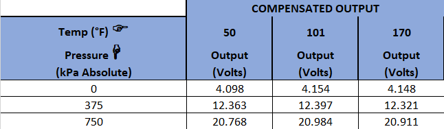
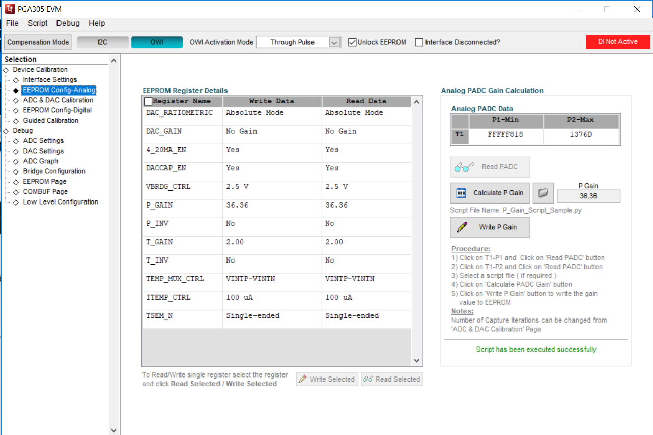
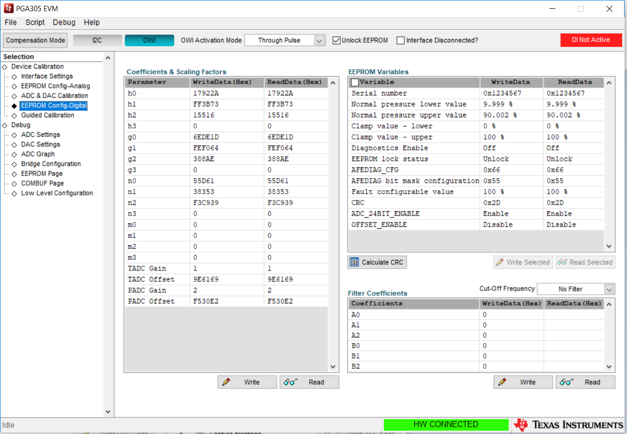
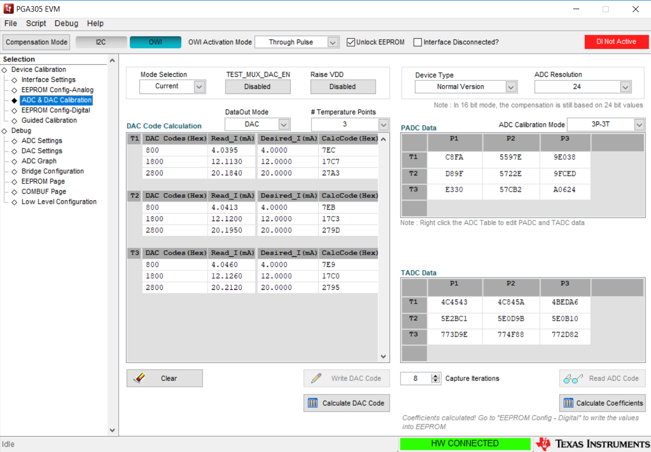
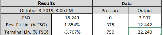
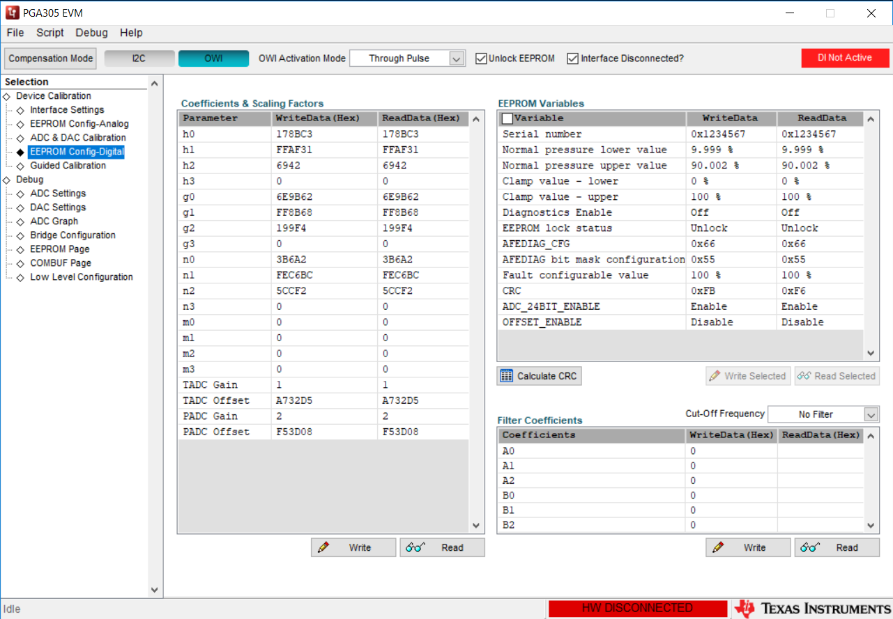
The data collected through temperature,  as shown in the attachment, appears to be reasonable. However,  after calculating the coefficients using the GUI and downloading to the chip,  the full scale output is way off.  A screen shot of the coefficients is also attached

Can you please tell me what I am doing incorrect?

 ed.

  • Hello Lori,


    Can you please attach the temperature data again? It seems to be lost from your original post.

    Additionally could you post a screen capture of the ADC&DAC calibration tab with the data that you collected for the calibration procedure? When you say that the full scale output is way off, do you mean that at the maximum pressure input, the DAC output is not at your expected value? Is the DAC output higher or lower than you expect, and does this offset stay the same for different pressure inputs, or is there some gain component to the error?


    Regards,

  • Below is the ADC&DAC calibration tab with the data collected.  

    The DAC output at each temperature is the same.  The PGA evaluation board, and therefore the PGA305 chip, is outside the oven so this makes sense.  

    Below is the data I collected at 50 degF after the coefficients were calculated and downloaded.  Please note that this is a 4 and 20 milliamp current loop.  I am currently collecting additional data at 101 degF and can post those results as well if it will help.

      Measured                      Expected

            Pressure                   Output                          Output

       (% of full scale)           (milliamps)                 (milliamps)

                   0                             4.095                         4.000 

                   50                          12.363                        12.000

                 100                          20.768                         20.000

  • The rest of the data collected through temperature is as follows...

  • Hi Lori,

    Thanks for the additional information. It looks like the calibration was completed successfully, so at this point the issue lies in accuracy of the calibration. The most common problem I see is that the temperature at which the calibration is validated is not exactly the same as the temperature at which it was calibrated. How long do you soak your test setup at each temperature point? For the best results, the temperature should be allowed to settle for 30 minutes to 1 hour after reaching the desired temperature. The simplest way to check would be to monitor the temperature through the GUI using the ADC Graph page. Once the temperature reading levels off for a while you can begin to take your calibration measurements. The same should be done when validating the calibration. The temperature should be allowed to settle.

    I would also suggest measuring the raw TADC data when validating the calibration to see if the temperature data matches the temperature at the calibration point. If the temperature is off, you will see some deviation from the expected output. This can also be useful for the pressure data, although the temperature is usually the more volatile of the two.

    Finally, make sure that the PGA305 is powered on for the entire calibration procedure. There is some small amount of self-heating that can affect the output (or the temperature input in the case of using the internal temperature sensor).

    Regards,

  • Is there some way to adjust what should be the 4 and 20 milliamp outputs by writing to a memory location using the GUI?  

  • Hi Lori,

    The output values are essentially determined as part of the coefficient calibration process. You can manually adjust the DAC values in the ADC & DAC calibration page, but it cannot be done separately from the rest of the calibration.


    Regards,

  • I tried the "Guided Calibration" and was still not able to compensate the unit through temperature.  

    I put a meter in the current supply to the external temperature sensor and found that the current supply to the external temperature sensor turns off when I switch from digital OWI to "Compensated" Mode".  This would explain why I can't compensate it.  

    We already determined that the external temperature sensor cannot be used in differential mode.  It also appears that the external temperature sensor cannot be used in single ended mode. 

  • Hi Lori,

    The guided calibration performs the same steps that you would do manually on the ADC&DAC Calibration page. If you navigate to that page during the Guided Calibration you'll see that it's entering the values into the table there as well.

    In my setup the current source continues to supply the temperature sensor even when the device is placed into compensation mode. Can you please post the Analog EEPROM settings, and the full EEPROM map? You can save a copy of the EEPROM map on the EEPROM page by reading the data and then right clicking to save the data.

    Regards,

  • I restarted the GUI and the problem went away.  However, after trying to recompensate the unit throught temperature, 50- 110-170 degF, I am still not able to get good data when I switch into compensated mode. 

    Attached are screen shots of the data and pressure vs milliamp output at 50 degF.

    The outputs should be 4 mA, 12 mA and 20 mA but the 12 and 20 mA outputs are significantly off.  I have been trying to compensate this unit for over a month and have not been able to get good results.  has the software been fully tested through temperature?

  • Hello Lori,

    Yes, the software and PGA305 device have been tested across temperature. Once the calibration is completed, if you return to the same calibration points, the output should be very close to what you have set as your desired output. If you are not seeing this, then the most likely cause is that your inputs are not the same as they were when you performed the calibration.

    I recommend trying some of the suggestions that I made in my post on Sep 27th above. 

    Also, the PGAIN setting that you are using is likely too low. The script that generates a PGAIN on the Analog EEPROM page currently has some issues, and it will always suggest 36.36. You should be able to double that gain at least (since the digital PADC Gain is after the calibration is being set to 2), and maybe increase it more. This should help with the calibration accuracy.

    Regards,

  • Thank-you for the information. I will adjust the gain.  This would increase the resolution but it seems unlikely that this would cause a 12% error at full scale as I'm seeing. 

    I am confident the soak time is not an issue as suggested in your last post. We are soaking for an hour which is what we use for all our product when we temperature compensate. 

    The data I posted showed that the full scale output of the unit was over 22 milliamps after compensation when it should have been 20 milliamps.  The compensated data of 22 milliamps was collected at the same temperature the uncompensated data was collected at and right after it was collected.  This was the last of 3 temperatures so the uncompensated data was collected, the calculations performed for the coefficients, the coefficients were downloaded, the unit was switched to compensated mode and the compensated data was collected. I am not clear why there would be error

    There has to be something I'm doing wrong if you're confident the software was tested for compensation at 3 temperatures.   All the coefficients are set to zero prior to collecting the uncompensated data with the exception of T_Gain,which is set to 1, and P_Gain, which is also set to 1.  Is this correct?

  • Hi Lori,

    Since the calibration is performed in digital interface mode, and you are reading the raw PADC and TADC data then it won't matter what is programmed into the coefficient space (including the digital PGAIN and TGAIN).

    Which digital interface are you using, I2C or OWI? If you are using OWI, what is your final system VPWR voltage? If it is higher than 5V, do you switch to that voltage after performing the calibration and before you validate the results of the calibration?

    There is a small amount of self-heating that can occur in the PGA305 at high DAC outputs, and when there is a higher VPWR voltage. This would typically only affect the results if the internal temperature sensor is used, but since you are using an external sensor it's not very likely. One way you could test this is to set your max DAC output to a smaller value and see if the accuracy improves. The self-heating should be reduced quite a bit with the device soldered onto a board with the powerpad connected.

    Regards,

  • Hello Scott,

    I am using the OWI.  I am supplying the evaluation board with 20 volts.  I don't know if this is stepped down on the eval board before it is fed to the PGA305 or not. I do not switch the supply voltage to the eval board at any point.

    I have set the unit up successfully when collecting data at a single temperature.  The PGA305 is able to generate 4 and 20 milliamps as expected.  The error I am seeing is over 10% when I try to use three temperatures to compensate.  The PGA305 generates 4 to 22 milliamps instead of 4 to 20 milliamps.  

    I have tried again with longer soak times at each temperature just to rule that out as per your previous suggestion.  It still generated 22 milliamps with full scale pressure applied. 

    I am running one more test with the P_ADC gain increased as per your suggestion as well. I don't anticipate that this will eliminate the 10% error but it will rule it out.

    I am looking at how I can generate the coefficients myself instead of relying on the software but am not sure I will have time to do this.  

  • I finished the run with P_ADC gain increased as per your suggestion.  Now the full scale output of the PGA305 is around 18.5 milliamps.  It still has significant error but the other direction.  (It was at 22 milliamps and should be 20 milliamps)

    You said the GUI has been tested for temperature.  Has it been tested using 3 temperatures for the compensation?  It really seems like there is an error in the calculations. 

  • Hi Lori,

    The Operating Characteristics (section 6.21) table from the datasheet shows the results of many calibrations in several different modes, including across temperature. For those tests, the internal temperature sensor was used and a bridge emulator provided inputs that could be easily replicated. There is a diagram in the PGA302 datasheet (http://www.ti.com/lit/ds/symlink/pga302.pdf) under the Application Data section which shows a similar bridge emulator to the one that was used to generate the data for the PGA305. All of the tests were performed with the EVM and the PGA305 GUI.

    I have also personally done calibration testing with a different sensor emulator board (http://www.ti.com/lit/an/sboa102a/sboa102a.pdf) that can be adjusted to match the real-world outputs of a specific pressure sensor along with a temperature sensor. This setup ensures each temperature and pressure is exactly repeatable, and using it with the PGA305EVM and GUI I was able to achieve datasheet performance. Since all of the analog inputs were carefully controlled and the output was as expected, I believe that the GUI calculated the coefficients correctly.

    As you mentioned, the zero points should be the closest to the expected output that is possible, so to have such a large deviation is unusual, especially if the pressure and temperature are carefully controlled. One more quick change that I can recommend is to set the PGA305 into Offset mode (you can do this in the EEPROM digital page and then make sure that Offset version is selected in the dropdown next to the number of bits on the ADC & DAC calibration page) for your calibration. The TADC and PADC digital offset values seem to be a bit high, so the Offset mode should help with that a bit at least. It's unlikely to clear up the problem, but it's another thing to check.

    Regards,

  • I tried a everything suggested, including changing the sensor,  and I was not able to get 4 and 20 milliamps out even just at a single temperature. 

    I have been using an external temp sensor, TMP61 as suggested in another post,  in single ended mode since there are issues with differential mode.  This morning I switched to the internal temperature sensor and was able to set the unit up to generate 4 and 20 milliamps output.  

    I am in the process of trying to temperature compensate using the internal temperature sensor. 

  • Hi Lori,

    Have you monitored the current through the thermistor at high temperatures? Does it stay constant? With your current setting of 100uA, the current source should have enough headroom to support the TMP61 up to the maximum operating temperature of the PGA305 based on measurements that I have done previously, but it's another potential cause. If you set the current output to 50uA do you see the same issue?

    Regards,

  • I had the current to the TMP61 at 50 uA.  I was monitoring it through temp and it seemed to be relatively stable. (meaning it would fluctuate in the nano amp range only.  

    I have collected the raw data using the internal temperature sensor and have downloaded the compensation coefficients.   The results at the first verification temperature are very good.  4.000 mA output with no pressure and 19.995 mA output at full scale pressure. 

    I am soaking at the second verification temperature but anticipate good results.  I have not managed to get this far using the external temperature sensor. 

    We would still like to use the external temperature sensor in our product.  I cannot get it to work but have eliminated some of the variables by proving the compensation using the internal sensor. 

  • Hi Lori,

    Thanks for the update. I'm not sure why the results with the external sensor are so much worse at the moment. Typically they will provide better results than the internal temperature sensor. As long as the current supply is stable, I would expect the thermistor's output to be stable as well. Please keep me updated with your testing.

    Regards,