This thread has been locked.

If you have a related question, please click the "Ask a related question" button in the top right corner. The newly created question will be automatically linked to this question.

FDC2214EVM: How to connect this EVM to my custom copper mesh sensor?

Part Number: FDC2214EVM
Other Parts Discussed in Thread: FDC2114, FDC1004, FDC1004EVM

Dear Sir/Madam,

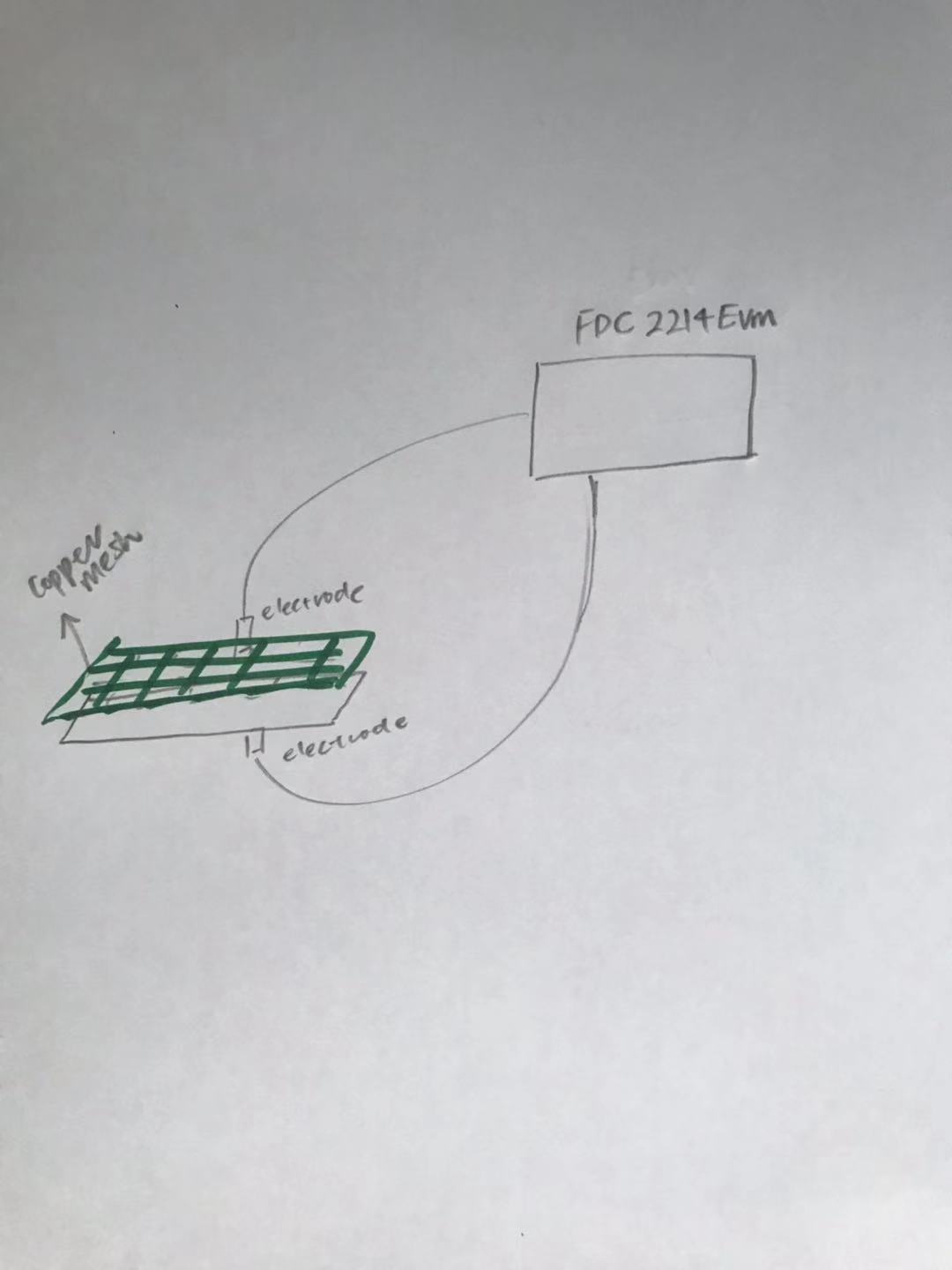
I having difficulties with understanding how to connect FDC2214EVM to my custom sensors. 

In this EVM, there are two capacitive sensors attached to it, which can be detached , do I need to attach this capacitive sensor to copper mesh? does this capacitive sensor act as an electrode in the picture shown

Then how detached captive sensor is connected to the EVM after detached, is it through the use of connection wires?

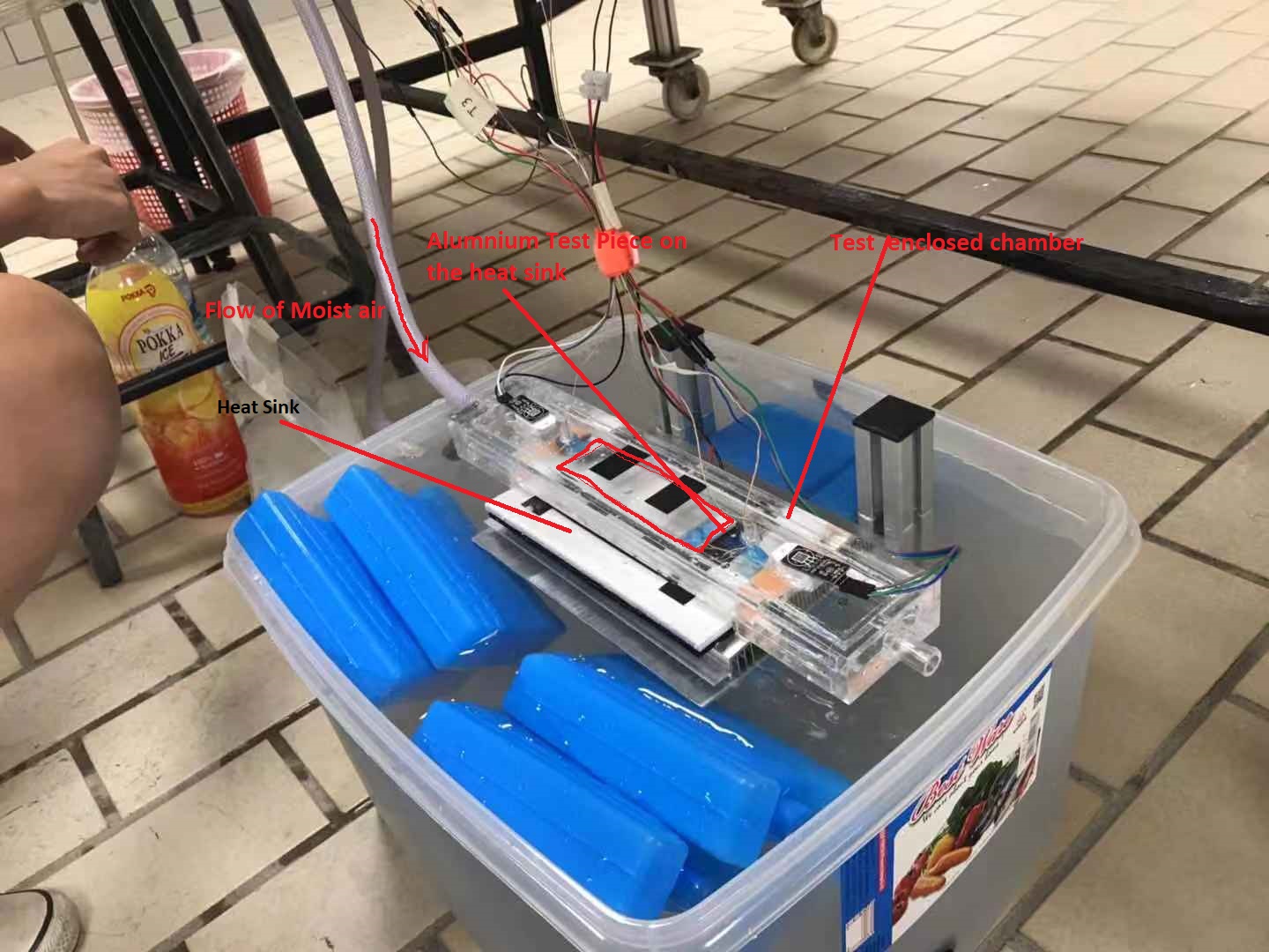
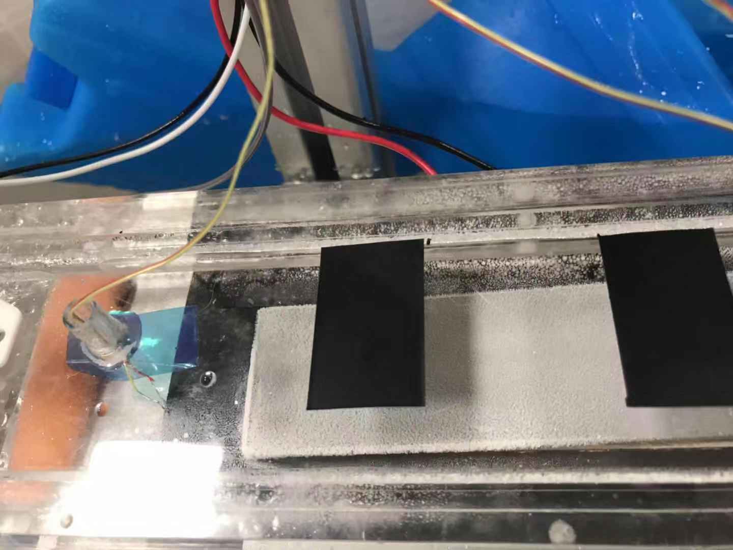
I am testing ice thickness on a flat plate in a humid environment. Kindly confirm with me whether my concept on using FDC2214EVM is correct.

Best Regards,

Qiuping 

  • Hi Qiuping,

    I apologize for some reason I am unable to see your picture. Can you please resend it ?

  • Dear Arjun,

    I would like to know if I can detach the sensor from evm, and attached to the surface of the test piece that I want to measure the ice thickness. If I can do so, how should I attached the sensor to my test surface( Do I just break it off from EVM and attached it to the copper mesh that is directly above my test surface?)? Does the sensor act like the capacitive electrode that has to attach to copper mesh and metal test surface individually and the capacitance felt will be sent back to evm without any wiring?

    Best Regards,

    QiuPing

  • Hi QiuPing,

    Thanks for sending the image. If the idea is to measure ice thickness build up in a humid environment. I highly recommend you use the FDC1004 series. The FDC2114 is really meant for proximity sensing that is used for hand gesture control applications. The FDC1004 does have capacitive active shielding which can help focus the sensing direction of a capacitive sensor and minimize any tuning that can be due to parasitics. The datasheet section 8.3.1 explains the complete description of how the shielding can help maximize sensor design and reduce variability in the parasitics. The FDC2114 does not have any active shielding and this requires several iterations of tuning the remote sensor or controlling the shielding externally. 

    There is also an application section on how FDC1004 can be used for ice thickness detection. http://www.ti.com/lit/an/slla355/slla355.pdf 

    As far as the connection goes just a wire from the CIn1 connection to the top of the copper mesh should be sufficient. 

     Let me know if this helps. 

  • Dear Arjun Prakash,

    http://www.ti.com/lit/an/slla355/slla355.pdf

    I have read through the set up, it is exactly what I want. But I need to clarify with you a few more questions.

    1, for the Lexan Poly carbonate sheet used in the experiment, does it act as a ground plate or shield plate ? Can I replace it with aluminium plate instead?

    2, for the copper sheet, what does it mean when the procedures in the documents said: "When cutting the copper sheet down to size, make sure not to short circuit the two layers of copper" I don't understand  how to make sure I  don't short circuit ?

    3, for the copper sheet sensor, can I attached to the bottom of my aluminium plate where I placed the copper sensor and the aluminium plate on a heat sink with cooling device? Should I leave a gap between the copper sensor and the heat sink? Will it caused any short circuit or inaccurate data analysis because I place the sensor directly on the heat sink.

    If not, could you kindly suggest a way to put my copper sensor?

    The attached are my experimental set up for your reference. The aluminium test piece is placed on the heat sink equipped with cooling chips to allow lowering the temperature of aluminum test piece. What I think is to put the copper sheet sensor directly below the aluminium test piece and attached the compound on the heat sink.

    Best Regards,

    QiuPing Wang

  • Hi QiuPing,

    Our expert on FDC is out of office. I will have our expert review the information and get back to you by end of next week. 

    The document clearly states that there has to be spacing between the copper plates if not you would be creating a short. Now adding AL will certainly create a short. What is the need for the AL to be attached as heat sink ? 

  • Dear Arjun,

    The objective of my experiment is to find out how surface roughness of aluminium plate will affect ice formation on the aluminium plate. So the medium here I want to test is aluminium.  Aluminium is attached to the heat sink because I want to bring down the surface temperature of the aluminium plate  so for ice to formed.

    Now I would like to use your capacitance method to measure the amount of ice formed with respect to time.

    I am not sure how does your FDC1004 can be attached to my aluminium surface?

    For example, the copper plates, where should I attached in my experiment set up, so that I can measure the ice formation on the aluminium plate?

    In your ice detection design, your medium used is plastic and your copper plate sensor is attached below the plastic.

    Best regards,

    QiuPing

  • Hello QiuPing,

    Thank you for your patience while I was out of office. I answered your questions below:

    1. The polycarbonate sheet acts as neither a ground plate nor a shield plate; it's not conductive. It just forms the base of the container for the liquid.I would not recommend replacing it with aluminum. If you did, make sure that the copper electrode is insulated from the aluminum.

    2. You want to make sure that the copper sheets are still separated when you are done cutting them down to size. There's no special technique.

    3. I do recommend not letting the heat sink (nor the aluminum plate) touch the copper sensor directly. You could either leave an air gap or add an insulative layer between the copper sensor and the heat sink/aluminum. You could even use more polycarbonate here.

    Best Regards,

  • Dear Kristin,

    Thank you for the information.

    Could you confirm with me that my set up is possible for your device to measure ice thickness?

    1, I want to check with you one more thing, can I place my copper sensor on top of the acrylic cover instead which is 5cm in height, so to create an air gap between aluminium and sensor. The acrylic is 5mm in thickness. Will I get inaccurate result for ice thickness measurement?

    2, For connection of copper sensor to FDC1004EVM, one side of it is connected to CHN1 through sodering the wire to CHN 1 and another side of the copper sensor is to sodering the wire to SHLD 1 in FDC1004 EVM. Am I correct with this understanding?

    Best Regard,

    QiuPing Wang

  • Dear Kristin,

    Any updates from you?

    Best Regards,

    QiuPing Wang

  • Dear Kristin,

    Thank you for the information.

    Could you confirm with me that my set up is possible for your device to measure ice thickness?

    1, I want to check with you one more thing, can I place my copper sensor on top of the acrylic cover instead which is 5cm in height, so to create an air gap between aluminium and sensor. The acrylic is 5mm in thickness. Will I get inaccurate result for ice thickness measurement?

    2, For connection of copper sensor to FDC1004EVM, one side of it is connected to CHN1 through sodering the wire to CHN 1 and another side of the copper sensor is to sodering the wire to SHLD 1 in FDC1004 EVM. Am I correct with this understanding?

    Best Regard,

    QiuPing Wang

  • Hello QiuPing,

    My apologies for the delayed reply.

    1. You will see some reduction in sensitivity with the additional 5mm spacing, but you should still be able to measure the ice thickness. You can read more about the tradeoffs between direct and remote sensing in this application note: http://www.ti.com/lit/an/snoa935a/snoa935a.pdf

    2. You are correct. One side of the copper sensor should be connected to CIN1 and the other side should be connected to SHLD1. Please note that the two sides of the copper sensor should not be shorted together; they should form a parallel plate capacitor.

    Best Regards,