Other Parts Discussed in Thread: FDC2214, FDC1004EVM
I have made a PCB with an FDC2212 for liquid level sensing. I have 4 electrodes - two on IN0a/b and two on IN1a/b, but they are on two different water tanks. (see photos). I filled one tank completely and it worked as expected. Then I started to fill the other tank, which is about 12" away, and the sensor reading on the first tank is going in the opposite direction as I fill the other tank! The FDC is counting higher on the full tank and lower on the empty tank as I fill it with water. Does that make sense? It seems almost like there's a setting in there somewhere that's making this happen. Maybe it was a mistake to connect both tanks to one FDC? The PCB is laid out just like the EVM. I have a 2214EVM, but I never thought to try it with both tanks connected to see what happens before I went ahead with all of this.
Here's a photo showing the setup. The black plastic enclosure has the FDC in it. You can see all 4 electrodes here. They are 1" wide and about 13" long spaced 0.5" apart. The tank on the left is full of water. The capacitance of the righthand tank did not change while I was filling the left tank. When I started to fill the righthand tank its value changes as expected, but the lefthand tank started to offset by almost the exact same amount!

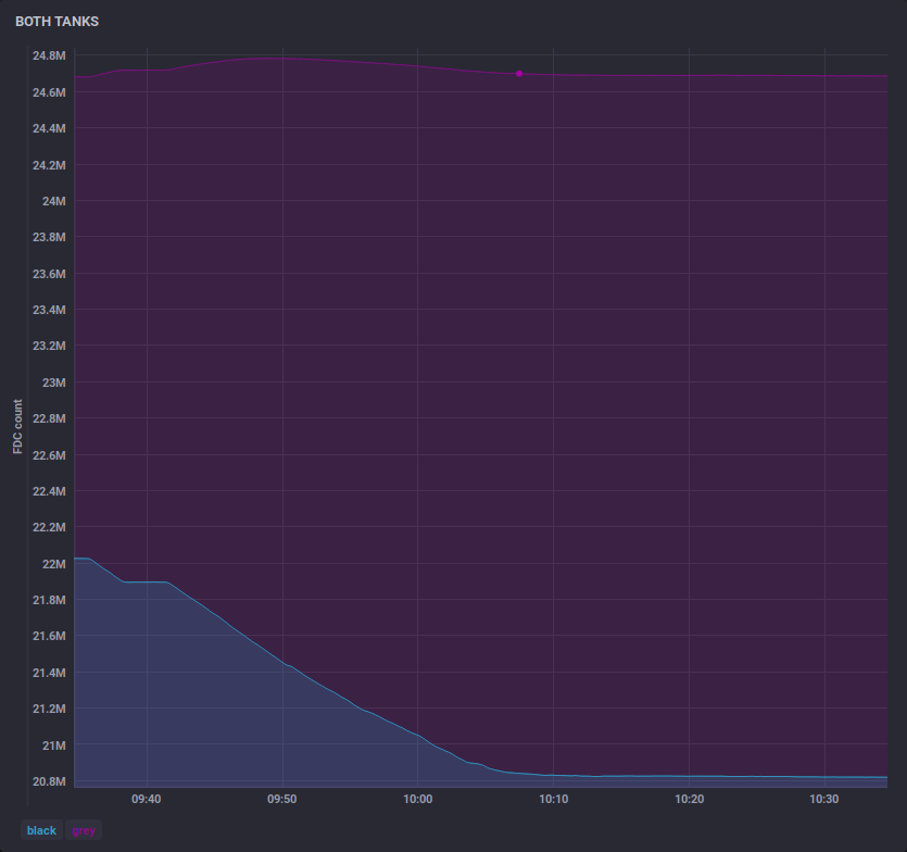
Here is a graph comparing the two tanks' raw FDC output values. The left tank on the graph is the left tank in the photo above. The steps in the graph are where I stopped filling the righthand tank!

Any ideas?