This thread has been locked.

If you have a related question, please click the "Ask a related question" button in the top right corner. The newly created question will be automatically linked to this question.

IWR1642BOOST: Strange ghost image in range-doppler processing

Part Number: IWR1642BOOST
Other Parts Discussed in Thread: IWR1642

To better understand how the radar signal processing work, I decided to implement TI's IWR1642 demo in Python. I grabbed the ADC data from mmWaveStudio using DCA1000, used the MATLAB visualization from postprocessing as the ground truth to check the correctness of my implementation. However, I am stuck at the range-doppler processing now with strange noises.

Below are two strange phenomenons I saw while comparing my range-doppler against mmWave Studio's PostProc. Note that left if my plot and right is MATLAB. my image is rotated 90 degree clockwise from ground truth but there should be just one target under the radar.

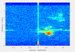
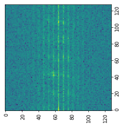
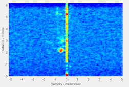
I often see either multiple mirrored "ghosts" of the original image, as shown in the first row, or strange columns, as shown in the second row, whereas the ground truth from PostProc is always clean.

I went back and forth to check the source code of the original demo, but the range-doppler is no more than just one FFT along the adc samples and one FFT along the chirps in one frame. Can anyone help me with this? Thank you!

  • Sorry the editor displays the different thing as the actual post. My plot the 1st and 3rd one w/ green-bluish background, 1st with strange ghosts and 3rd with strange cloumns. The 2nd is the range-doppler from mmWave Studio PostProc using the same data as 1st and 4th shares the same data with 3rd one.

  • I've asked an expert to look into this and we should have an answer for you sometime next week.


    Cheers,

    Akash

  • Hi, 

    Probably you can compare the ADC data.  You probably used the raw data, which contains the package header information.   You may need to run RawFileFormat.exe to change the raw data into the true binary data for process.  

    system(['RawFileFormat.exe 2 ' dataLoadingPreFileName ' ' dataLoadingFileName ]);    

    You can find this exe file under radar studio directory: C:\ti\mmwave_studio_02_01_00_00\mmWaveStudio\PostProc

    Or you can click on the post processing button, it will run this script, take the xxx_raw_0.bin and generate the output file xxx.bin.  Let me know if it helps.

    Best,

    Zigang

  • Hello Zigang,

    Thanks for the reply. I will go try your proposed solution and come back to you, but I'm not quite sure if that is the problem. Here is my workflow: I captured the data, ran the PostProc for the Packet_Reorder_Zerofill on DCA1000 data. Then I funnel this data separately to the PostProc MATLAB visualization and my python practice code for the sanity check, then the problem showed up. I check the document http://www.ti.com/lit/an/swra581b/swra581b.pdf about how to convert the ADC data of DCA1000 and it doesn't say much except the reordering. Besides, the dimension of my captured frames work out with the the number of the bytes of the captured ADC data.

  • Hello Zigang,

    In fact the data I have is the converted data from raw ADC by clicking the PostProc button so I assume the data itself is correct. Can you walk me through the steps to get the range-Doppler to make sure it's correct?

    1. Given (256, 4, 128) ADC data, which is (numChirpsPerFrame, numPhysicalReceivers, numADCSamples), run FFT on 128 first to get range information.

    2. Interleave the chirps based on Tx so that data will be (128, 8, 128), (numChirps, numVirtualReceivers, numRangeBins).

    3. Run FFT on numChirps to get the Doppler information.

    4. Take absolute value, log2 and sum over numVirtualReceivers to get (numDopplerBins, numRangeBins) to get the range-Doppler.

    5. FFT shift over numDopplerBins for visualization purpose, and then plot the final data.

  • Hi Zigang,

    I figured out the problem. It's nothing related to DSP or data processing in the mmWave Studio side, it's me reading the binary data as uint16 instead of int16. I revisited the doc and realized that the binary is in 2's complement.