This thread has been locked.

If you have a related question, please click the "Ask a related question" button in the top right corner. The newly created question will be automatically linked to this question.

IWR6843: What causes the so called undershoot or overshoot of frequency during ramp?

Part Number: IWR6843


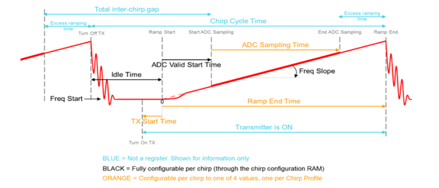
In related post, it encourages a positive tx Start Time in order to:

"Tx start time +ve: it gives the advantage to avoid undershoot or overshoot of frequency during ramp."

We (electronics engineers) can not understand what would cause this under/overshoot.

Can you explain what causes it?

We try to understand in order to decide on what value we should set for the Tx Start Time.

  • Hi Johanwww,

    I've asked an expert to look into this and we should have an answer for you in the next few days.


    Cheers,

    Akash

  • To clarify, we do understand what causes the overshoot at the end of the ramp.

    But not the beginning of the ramp, and how to pick TxStartTime.

  • Hello, 

         Overshoot and undershoots are due the inherent behavior of the Synthesizer (Which is a form of a PLL). 

    Synthesizer loop dynamics causes frequency overshoot/undershoot depending upon the chirp configuration. This is common behavior in the PLL/Synthesizer designs.

    You could refer to below app-note (Section 5) Chirp Timing Parameters. 

    http://www.ti.com/lit/an/swra553/swra553.pdf

    Typically larger the RF sweeping bandwidth higher the settling time needed for the Synthesizer to lock to desired frequency. 

    There could be a trade-off between the frequency error vs settling time.

    To avoid spectral emission of these overshoot and undershoot into antenna one could blank the PA by adjusting the Tx start time. w.r.t chirp timing. 

    As far as Radar is concern, it would capture only ADC sampling time, However outside this region we need to ensure we are within the emission requirement of regulatory body depending upon the country/region it's being operated. Tx start time knob facilitates to avoid spurious emission if any.   

    Thanks and regards,

    CHETHAN KUMAR Y.B.

  • We might misunderstand you, so to make sure we talk about the same thing:

    After ramp down the synthesizer locks to desired frequency / starting frequency. This has some undershoot issues that we need to handle. We know about these. And it need some settling time (idleTime) to settle.

    But once it has settled there should be no more need for any further settling time.

    Then at time 0, the chirp starts and the frequency starts to increase.

    Why is this not a linear increase in the beginning?

    We have seen in mmwave studio how it recommends the adcStartTime to avoid the settling at the beginning of the chirp, but we dont know what it is that should settle.

    And we have analyzed the output from the IWR6843 and seen some non-linear behavior in the beginning, see figure 2. These are the ones we are interested in. We can not understand how these can be due to the settling of "Synthesizer to lock to desired frequency".

    Are we misunderstanding your answers?

  • Hello,

        Non-linearity at the beginning of the ramp is coming from the Synthesizer, as synthesizer is beginning to ramp from the point you have highlighted.

    However, non-linearity at this point is very small 0.1 to 0.01%, which is coming from the synthesizer itself. By adjusting the "ADC start time" you could ensure these non-linearity not captured in the ADC output data. This is also a trade-off, by increasing the ADC start time you would be marginally losing the maximum allowable sweeping RF bandwidth, which reduces range resolution marginally.  

    But when you review ADC output at this point in time, you also need to consider other settling factors into account for higher non-linearity such as:

    1) ADC sampling rates (for smaller ADC sampling rates  it causes higher setting time in the DFE chain,This comes from digital pipeline delays in the sigma-delta ADC decimation filter)

    2) HPF step response settling, which is a function of HPF corner frequencies. 

    3) as you pointed out Synthesizer PLL ramp-up settling time, which is a function of ramp slope.

    Hence there is a trade-off between the settling time desired vs amount of non-linearity that could tolerable at system level.  For this trade-off mmWave studio offers different % settling (90%, 95%, 99%) vs recommended values that could be set for Idle time, ADC start time, Ramp end time. 

    For more details you could refer to "Programming Chirp Parameters in TI Radar Devices"  app-note  http://www.ti.com/lit/an/swra553/swra553.pdf

    Thanks and regards,

    CHETHAN KUMAR Y.B.