Q1. mmWaveLink_example usage/porting on External processor
MmWaveLink_example provides reference code to control AWR1243/P over SPI. This specific application uses SPI-to-USB FTDI emulator interface on PC to communicate with AWR1243.
HW connection: 4-SPI, HostIRQ lines, SOP lines and nReset line control which need to be connected to external Host Processor. Please refer ProcessorSDKRadar_UserGuide.pdf from TI Processor Radar SDK for more hardware connection.
SW setup: Please refer these threads dsicussing about similar topic
https://e2e.ti.com/support/sensors/f/1023/p/839686/3105534#3105534
https://e2e.ti.com/support/sensors/f/1023/p/799855/2982538#2982538
https://e2e.ti.com/support/tools/sim-hw-system-design/f/234/t/828947
https://e2e.ti.com/support/sensors/f/1023/p/797855/2952265
Q2. How to capture ADC data using mmWaveLink_example AWR1243+DCA1000EVM?
- Set AWR1243BOOST in SOP-4 mode.
- Connect AWR1243BOOST with DCA1000EVM.
- Configure the DCA1000EVM using mmWave Studio (steps here) or use DCA1000EVM_CLI_Control.exe from mmWave Studio v2.1 to do this step.
- Execute mmWaveLink_example on the PC which configure the device, make sure that you have change the no of frames to infinite in mmwaveconfig.txt (numFrames=0) before starting it.
- DCA1000EVM should able to capture the data now.
https://e2e.ti.com/support/sensors/f/1023/p/826017/3055751
Q3. How to debug AWR1243/AWR2243 device when Logger or JTAG pins are not available but RS232 line is accessible?
Answer: On a closed board where AWR1243/AWR2243 device is connected with Host over SPI, debugging AWR1243 might be a difficult task. RS232 lines RS232_TX [PIN: N6] RS232_RX [PIN: N5] which is used for flash programming, can be used to read specific memory of the device.
By reading device memory space we can find the device status and cause of issue Host is facing.
Using TeraTerm we can access device register space. Here are the steps to setup this tool
-
To setup Tera-Term to read/write register over RS232 from AWR1243/AWR2243 in SOP-4 mode(functional mode)
- Connect TeraTerm over 'Application/UART' COM port @115200 baud rate. This COM port name is available while connecting RS232 lines over XDS110 USB-UART emulator
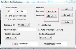
- And goto terminal->setup and set new-line option as in below snapshot
-
Command to read register (make sure all characters are in a small case and address must be in hex but without '0x' prefix)
‘rd <register-address>’
e.g. rd ffffe1ec [expected return value 00000028]
Other memory regions which need to be read in case of any issue.
-
- MibSPI RAM : 0xFF0E0000 to 0xFF0E01FC (TxRAM); 0xFF0E0200 to 0xFF0E03FC (RxRAM) to check the SPI command/response bytes. These two memory range are circular buffer/RAM for MibSPI.
- BSS power up status: 0xFFFFE1EC ; output value 0x000F0028 (bit 16:19) says BSS powered on successfully.
- BSS to MSS mailbox: 0xF0601000 to 0xF06017FF; MSS to BSS mailbox: 0xF0602000 to 0xF06027FF
- HostIRQ status: 0xFFFFE144 (MISCCTL) : if b23:16 = 0xAD then HOST_IRQ is High.
Q4. How to capture MSS or BSS log with AWR1243/AWR2243 device?
Answer: Many of times to debug critical issues with AWR1243/AWR2243, we need MSS or BSS logs. In AWR1243 MSS or BSS dumps the debug log over UART. Device Pin R5: MSS_LOGGER, R4: BSS_LOGGER need to connect over UART-to-USB emulator to PC.
Connect TeraTerm to one of the COM port connecting to MSS/BSS logger. MSS dumps log at 115200 (for AWR1243)/ 921600 (for AWR2243) baud rate and BSS dumps log at 921600 baud rate, so set a similar setting in TeraTerm.
If using AWR1243BOOST with DevPack/DCA1000EVM then MSS log comes at 'XDS110 Auxiliary Data COM port' and BSS log comes at 3rd COM port emulated from DevPack board.
Note:
a. On DCA1000EVM board, BSS logger pin is not connected with AWR device, so with DCA1000EVM you won't get BSS log. Only MSS logger which is routed over AWR EVM.
b. BSS log data is only available after BSS is powered on from the Host or mmWave Studio.
The user needs to capture the TeraTerm log in binary format to a file (TeraTerm menu File→Log, give filename and select Binary option checkbox in the popup window). This file needs to be shared with TI mmWave Team to parse and analyse it.
While providing the captured log user must need to mention the exact MSS and BSS version to parse it correctly.
Q5 How to create a Triangular Waveform from mmWave Sensor device?
Please refer this thread : https://e2e.ti.com/support/sensors/f/1023/p/832554/3090039#3090039
Q6 Please explain advanced frame configuration of mmwave sensor?
https://e2e.ti.com/support/sensors/f/1023/p/851842/3150523#3150523


