This thread has been locked.

If you have a related question, please click the "Ask a related question" button in the top right corner. The newly created question will be automatically linked to this question.

TDC1000-C2000EVM: 160 kHz Ringing on TX and RX

Part Number: TDC1000-C2000EVM
Other Parts Discussed in Thread: TDC1000,

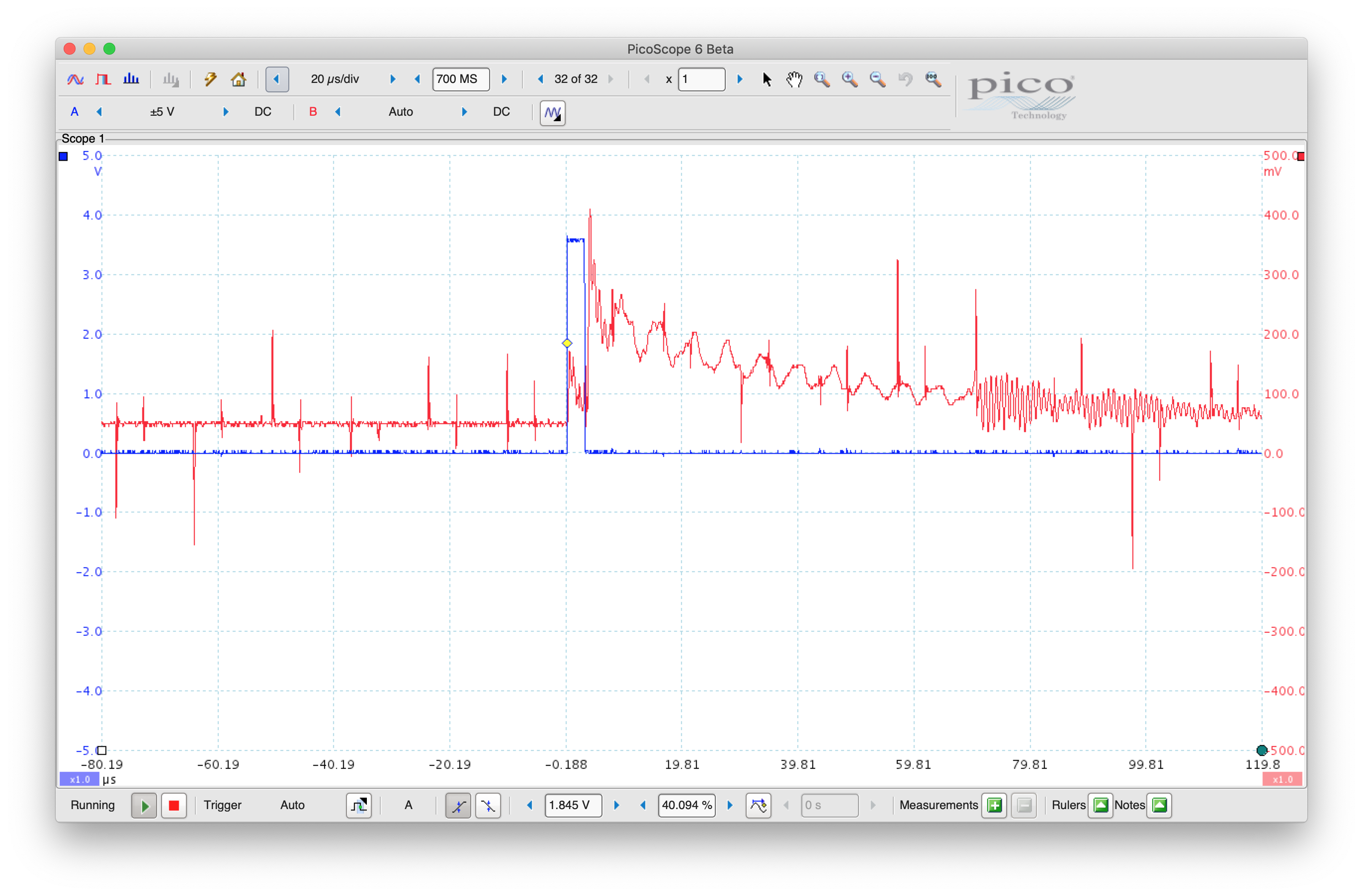
I am seeing generally noisy signals including a very pronounced ringing at ~160 kHz on the TX signal.  These noise effects appear to be swamping out the actual acoustic signals and I have been unable to get the TDC1000 to correctly generate STOP pulses as expected.  In general, my scope traces don't look nearly as clean as I have seen in the documentation or in most other people's posts on this forum. Any ideas what is going wrong here?

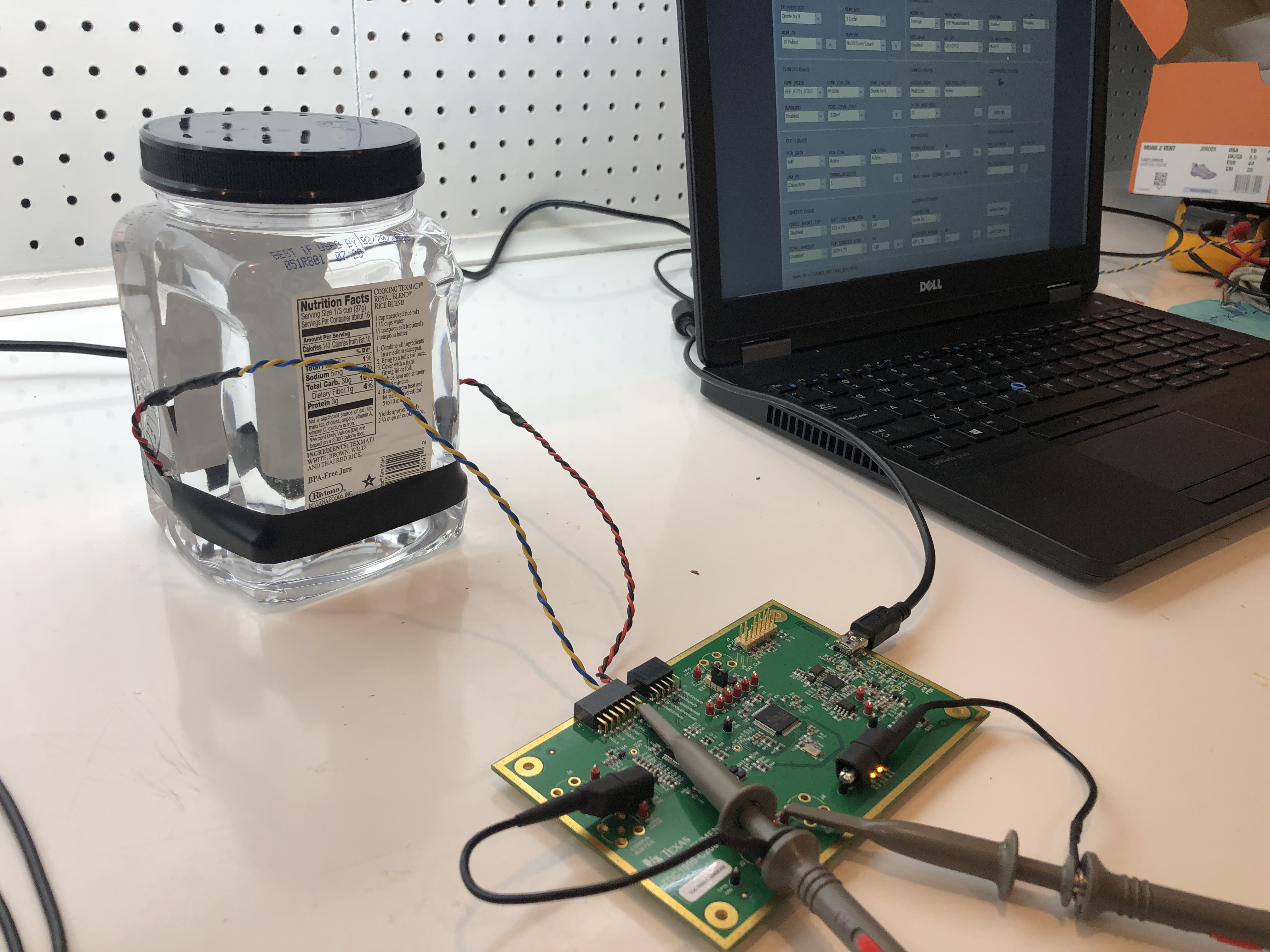
I am using the TDC1000-C2000EVM with two 1 MHZ Steminic transducers (SMD15T21R111WL).  The two transducers are mounted with acoustic coupling gel to opposite sides of a plastic water-filled container ~100 mm apart. Sensor 1 is connected to TX1 and GND.  Sensor 2 is sometimes connected to TX2 and GND, but at other times just connected directly to an oscilloscope probe.  Oscilloscope probes are set to 10X.  The TOF_MEAS_MODE is Mode0.  

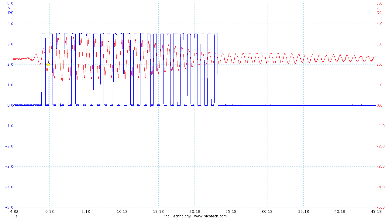
In the screenshot below, blue is the TX1 signal and red is the unconnected sensor 2 (just the oscilloscope) hearing the transmitted signal ~70 us later after propagation through 100 mm of water.  The lower frequency ringing is approximately 160 kHz.

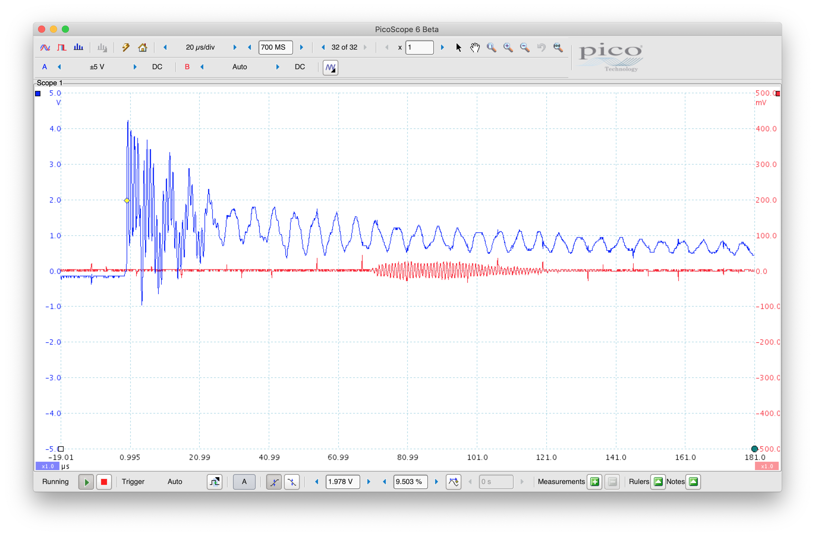
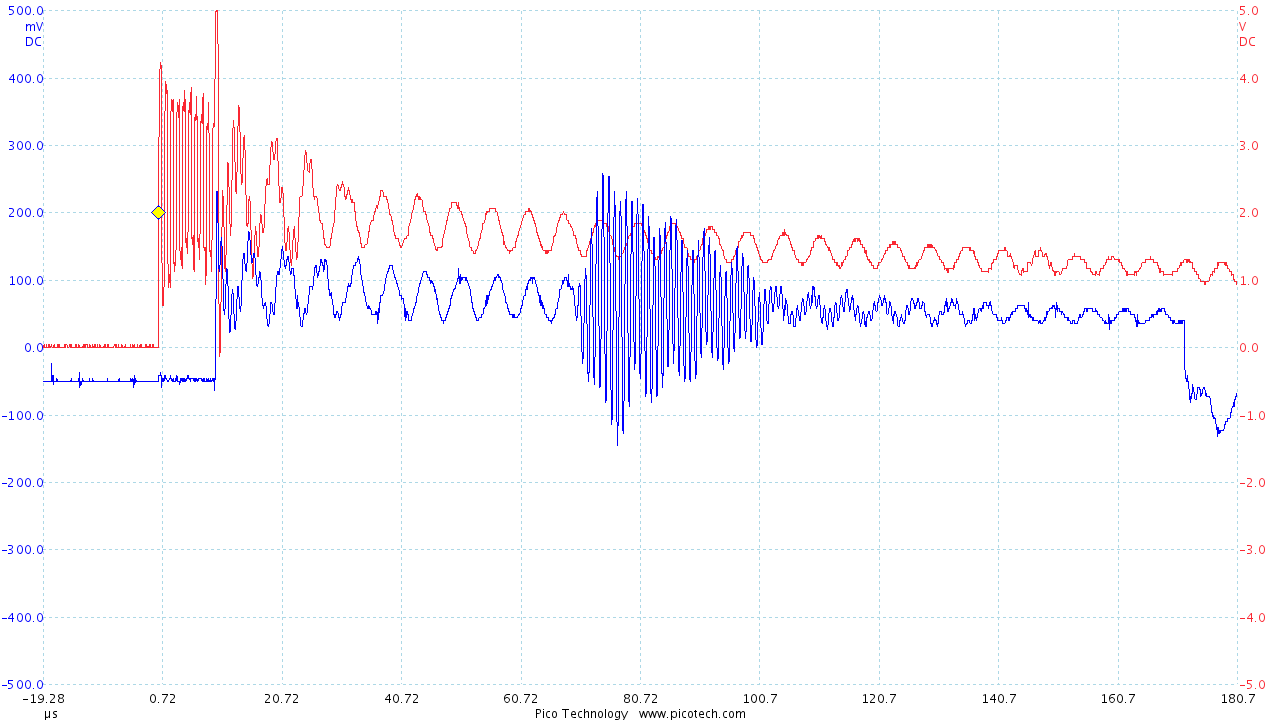
In the next scope trace (below), I have moved the blue channel to the COMPIN buffer.  Note several things:

  • COMPIN is picking up some of the excessive ringing from the TX signal.
  • COMPIN goes completely quite after ~20 us

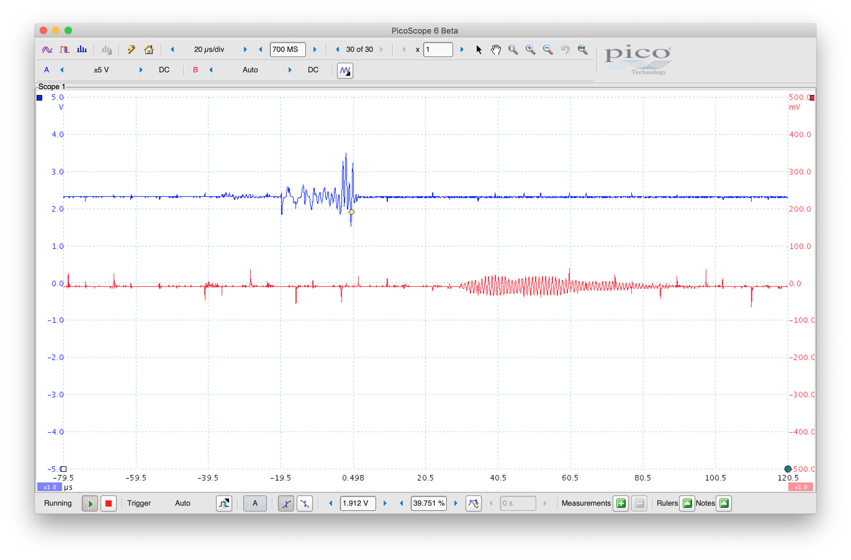
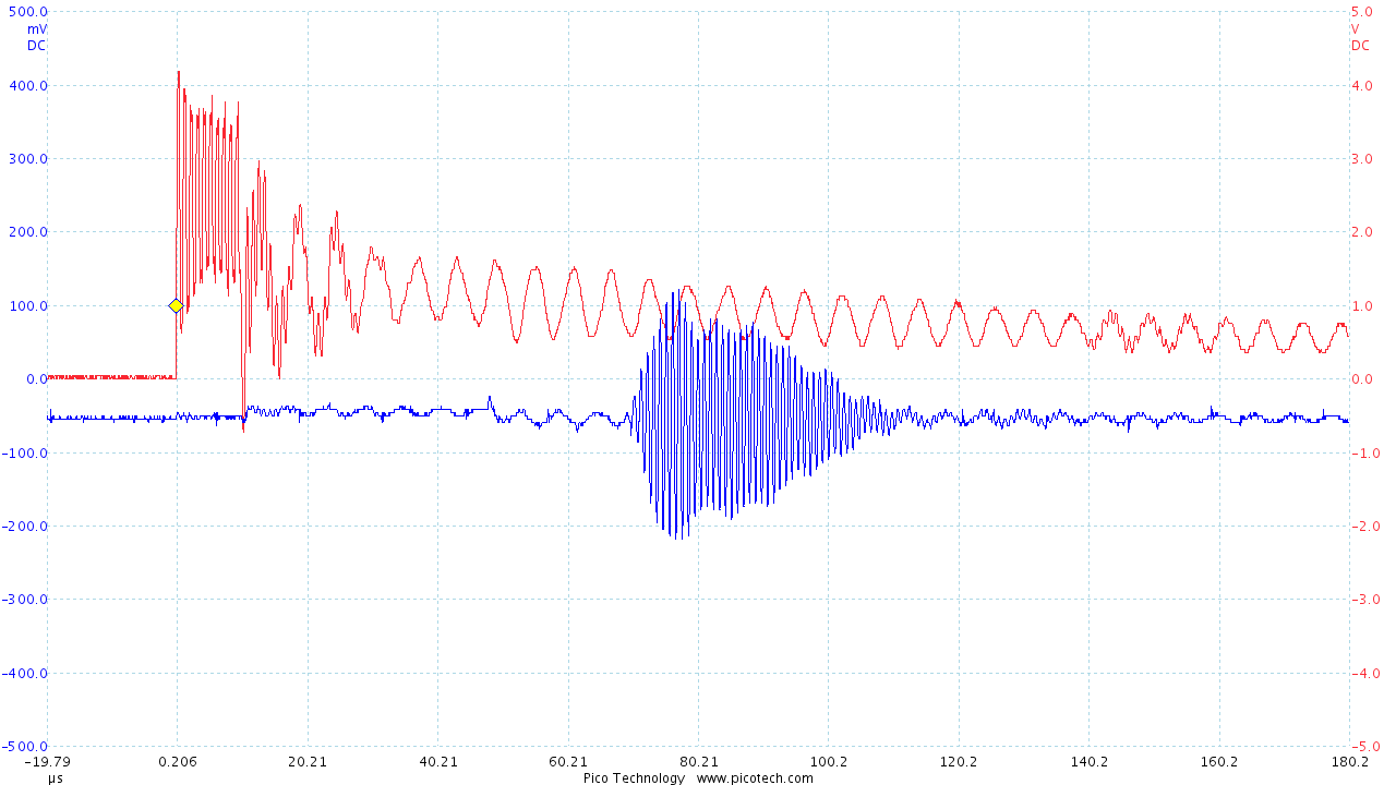
In the next experiment, blue is connected to START and red is connected to the otherwise unconnected sensor 2.  Again, the transmitted signal can be seen arriving at sensor 2 ~ 70 us after START.

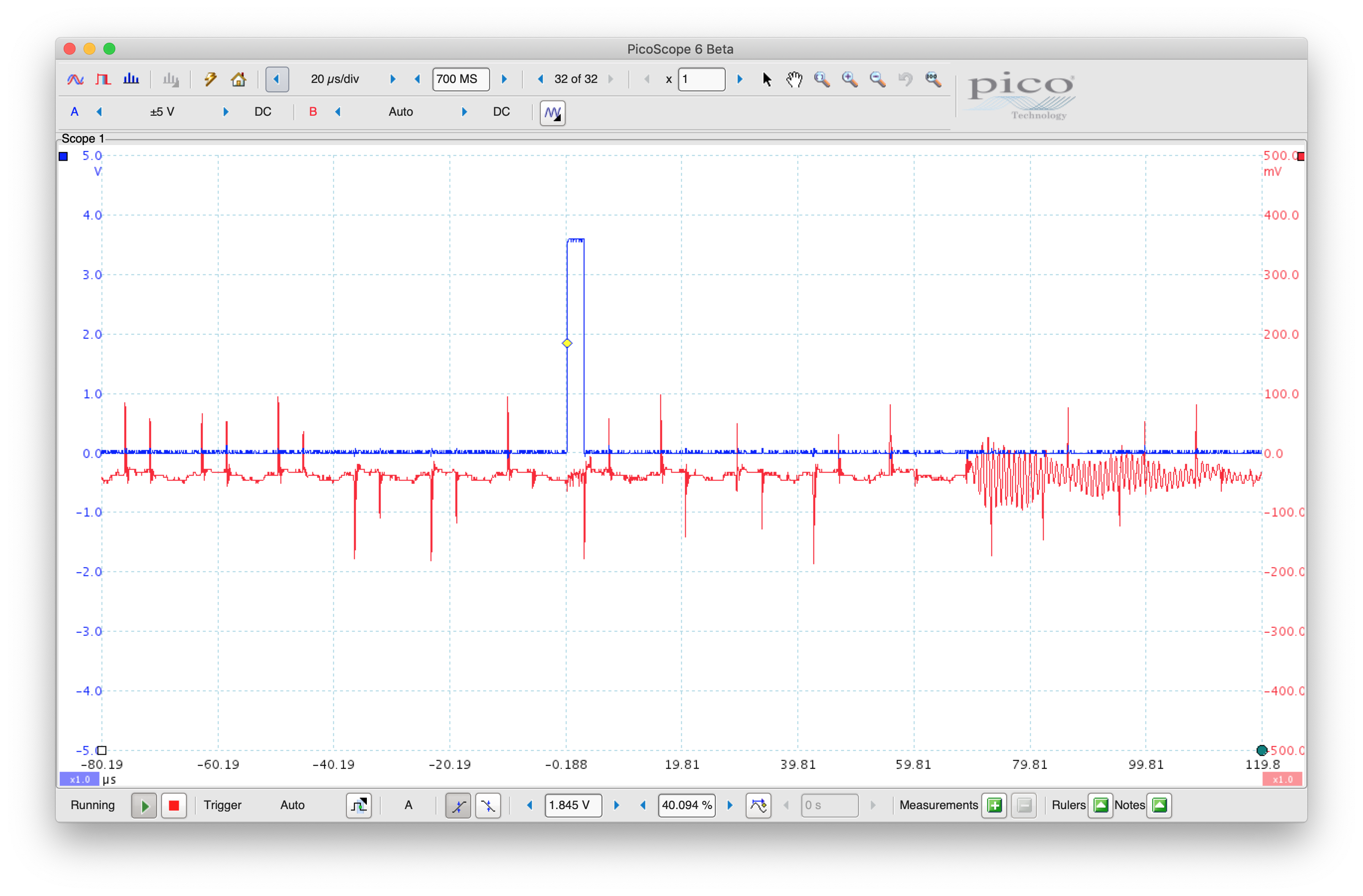
Below is the same test, but sensor 2 has been connected to TX2 and GND.  The wavefront can still be seen arriving ~70 us after START, but now we see the ~160 kHz ringing coupled from TX1 onto TX2.  Because of the scope trace above, I do NOT believe that this is acoustic coupling between the sensors, but rather some sort of electronic coupling on the TDC1000-C2000EVM board.

  • Neal,

    Let me review the data that you have attached, I will respond by Friday this week.

  • I reran these experiments today with a clearer head and made some improvements.  The 160 kHz ringing is still my major issue, but hopefully, I have it a bit more isolated now.

    I shorted the leads going to the transducers from ~0.5 m to ~0.2 m and twisted the wires more tightly.  This greatly reduced my 60 Hz noise as well as some of the higher frequency spikes observed in the previous scope traces.

    First, I captured the TX1 pin with no transducer attached.  The TDC1000 appears to be generating 10 relatively clean square pulses. In all of the following plots, NUM_TX is set to 10 pulses.

    Connecting the 1 MHz transducer to TX1 and GND, but leaving the transducer in air, we immediately see the 160 kHz rining (as well as continued 1 MHz ringing) show up.  This shows that the 160 kHz signal is not caused by some astonishingly fast dynamics of my water container.

    Attaching the transducer to my water container with electrical tape and acoustic coupling gel, the 1 MHz signal gets damped away much more quickly but the 160 kHz ringing persists.

    Now, we can look at TX1 and VCOMIN to see that some of the noise from the TX1 pin is in fact showing up on VCOMIN.  Note that this is far too soon for the transducer to be picking up an actual acoustic echo. 

    Additionally, I removed the oscilloscope probe from the TX1 pin and saw no change on VCOMIN.  This helped convince me that the crappy signal I am seeing on TX1 is real and is not an artifact of or caused by my oscilloscope.

    Next, I connected a second 1 MHz transducer to TX2 (RX1) and affixed it to the opposite side of the water container with electrical tape and acoustic coupling gel.  Here you can see TX1 and TX2 with the TDC1000 in TOF_MEAS_MODE = Mode 0. Notice that the 160 kHz signal couples from TX1 to TX2 immediately and is not subject to the 70 us acoustic delay through the water.  In the good news department, we see the transmitted acoustic signal arrive 70 ms later at the second transducer, just as expected.

    Switching the TDC1000 into TOF_MEAS_MODE = Mode1 dramatically reduces (but does not eliminate) the coupling of the 160 kHz signal from TX1 to TX2.  My hypothesis is that this is somehow related to which channels are connected when internally during the transmit sequence.  

    The downstream processing from here appears to be working as expected.  Below, we see VCOMIN and STOP signals with TOF_MEAS_MODE = Mode1

    In conclusion, the overwhelming problem that I am still having is the presence of a large 160 kHz ringing on the transmit pin as soon as I connect the 1 MHz transducer to the TDC1000.  Any help further troubleshooting this would be greatly appreciated.

    Neal

  • As an additional data point, I tried using a different 1 MHZ Steminic transducer (SMD10T2R111) that is 10 mm in diameter as opposed to 15 mm for the original SMD15T21R111WL and observed a slightly different ringing frequency. Note that both of these transducers are sold as 1 MHz transducers and only appear to differ in their diameter.

    • with 15 mm diameter transducer ringing is observed at 160 kHz
    • with 10 mm diameter transducer ringing is observed at 250 kHz

    With one of each type of transducer plugged into the TDC1000-C2000EVM and transmitting on Ch 1 (mode 1), I saw TX1/RX2 ringing at 160 kHz while TX2/RX1 was simultaneously ringing at 250 Hz.  

  • Neal,

    This lower frequency resonance you're observing is a decay artifact of the transducer, and not TDC1000 necessarily device related. Some transducers have multi-resonance frequencies, which is why you are likely seeing a 160kHz and 250kHz decay for the 15mm and 10mm diameter transducers respectively. One thing you can try to minimize the decay ring frequency is place a resistor in parallel to the transducer. The concept and example values for a damping resistor is explained in the PGA460 Ultrasonic Module Hardware and Software Optimization app note, section 3.4. I always use 10kOhm as a default value. Alternatively, you can try using a different transducer that doesn't have multiple resonance frequencies.

    For you information, we have a new ultrasonic sensing IC being released soon; the EVM for which is already available. See the following post for more details: https://e2e.ti.com/support/sensors/f/1023/p/851617/3202406#3202406