This thread has been locked.

If you have a related question, please click the "Ask a related question" button in the top right corner. The newly created question will be automatically linked to this question.

AWR1642: AWR164BOOS object detection over can

Part Number: AWR1642

Hi All,

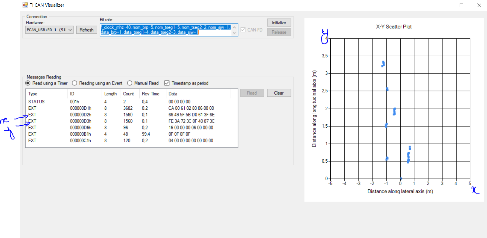
I'm using awr1642 boost Rev B, I'm actually  testing object detection over CAN lab, On th MMWAVECANVISUALIZER app, there's message reading  and (x,y) plot. I would like to plot Range-Doppler heat map instead of (x,y) plot. Also I have some questions :

  1. How to interpret (understand) messages reading ? what do they present?
  2. Does awr1642boost send only (x,y) over CAN bus (I need targets velocities (doppler))?

Thank you

  • Hi,

    Please note that every demo we provide can be updated to send the data over CAN.

    We provide the demo object data  over CAN as an example.

    Please feel free to update this demo to send the heat map

    You would need to develop the PC gui to accommodate the data sent.

    Thank you

    Cesar

  • Hi Cesar !

    Thank you for your reply

    I had read the document "adding can bus to an existing project", but this is not my issue. I'm trying to locate on the ODOC lab MSS main the selection of

    the data to be sent via CAN BUS ( x,y in the existing lab) and then choosing heatmap ?! 

    Thanks

  • Hi,

    You would have to modify in the following file the "guiMonitor" command

    C:\Users\a0323124\TIREX\mmwave_automotive_toolbox\labs\lab0005_object_data_over_can\odoc-target\mss\cli.c

    The "guiMonitor" command is described in the SDK 2.1 UG

    C:\ti\mmwave_sdk_02_01_00_04\docs\mmwave_sdk_user_guide.pdf

    CLI_MCB     gCLI;
    #define CLI_BYPASS 1
    #define MAX_RADAR_CMD               28
    uint8_t* radarCmdString[MAX_RADAR_CMD] =
    {
        {"sensorStop \n\r"},
        {"flushCfg \n\r"},
        {"dfeDataOutputMode 1 \n\r"},
        {"channelCfg 15 3 0 \n\r"},
        {"adcCfg 2 1 \n\r"},
        {"adcbufCfg -1 0 0 1 0 \n\r"},
        {"profileCfg 0 77 7 7 58 0 0  68 1 256 5500 0 0 30 \n\r"},
        {"chirpCfg 0 0 0 0 0 0 0 1 \n\r"},
        {"chirpCfg 1 1 0 0 0 0 0 2 \n\r"},
        {"bpmCfg -1 0 0 1 \n\r"},
        {"frameCfg 0 1 32 0 100 1 0 \n\r"},
        {"lowPower 0 1 \n\r"},
        {"guiMonitor -1 1 1 1 0 0 1 \n\r"},
        {"cfarCfg -1 0 2 8 4 4 0 5120 \n\r"},
        {"cfarCfg -1 1 0 8 4 4 0 5120 \n\r"},
        {"peakGrouping -1 1 0 0 1 224 \n\r"},
        {"multiObjBeamForming -1 1 0.5 \n\r"},
        {"calibDcRangeSig -1 0 -5 8 256 \n\r"},
        {"extendedMaxVelocity -1 0 \n\r"},
        {"clutterRemoval -1 0 \n\r"},
        {"compRangeBiasAndRxChanPhase 0.0 1 0 1 0 1 0 1 0 1 0 1 0 1 0 1 0 \n\r"},
        {"measureRangeBiasAndRxChanPhase 0 1.5 0.2 \n\r"},
        {"nearFieldCfg -1 0 0 0 \n\r"},
        {"CQRxSatMonitor 0 3 4 127 0 \n\r"},
        {"CQSigImgMonitor 0 63 8 \n\r"},
        {"analogMonitor 1 1 \n\r"},
        {"lvdsStreamCfg -1 0 0 0 \n\r"},
        {"sensorStart \n\r"}
    };