Because of the Thanksgiving holiday in the U.S., TI E2E™ design support forum responses may be delayed from November 25 through December 2. Thank you for your patience.

This thread has been locked.

If you have a related question, please click the "Ask a related question" button in the top right corner. The newly created question will be automatically linked to this question.

IWR6843AOPEVM: IWR6843AoP Bounce and Refresh Time on Detected Objects

Part Number: IWR6843AOPEVM

Hello;

I am working on the code "mmwave_sdk_68xx_aop_hwa".Detected objects sometimes shows bounce. sometimes I don't get the right printouts. And in rare cases, update times may be delayed. I started to examine the sample code. I could not clearly find out where the chirp modulation signal is generated and how the receive signal is evaluated. "mmwdemo_rfparser.c" library, I can evaluate variables and contents according to antenna geometry. However, I could not find the chrip signal generated according to the frequency range. 

Maybe a little detailed question, but can you help?

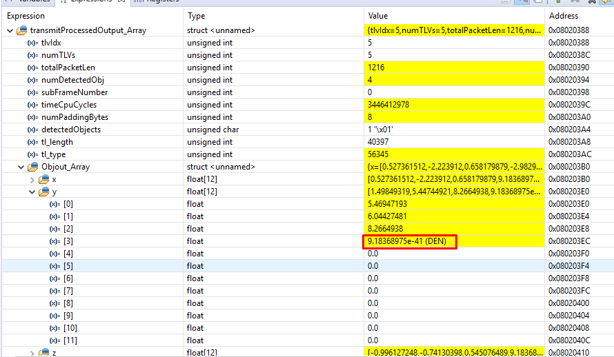
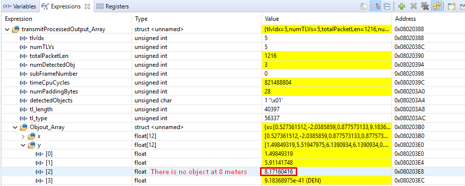
Below are some images from the Debug screen.

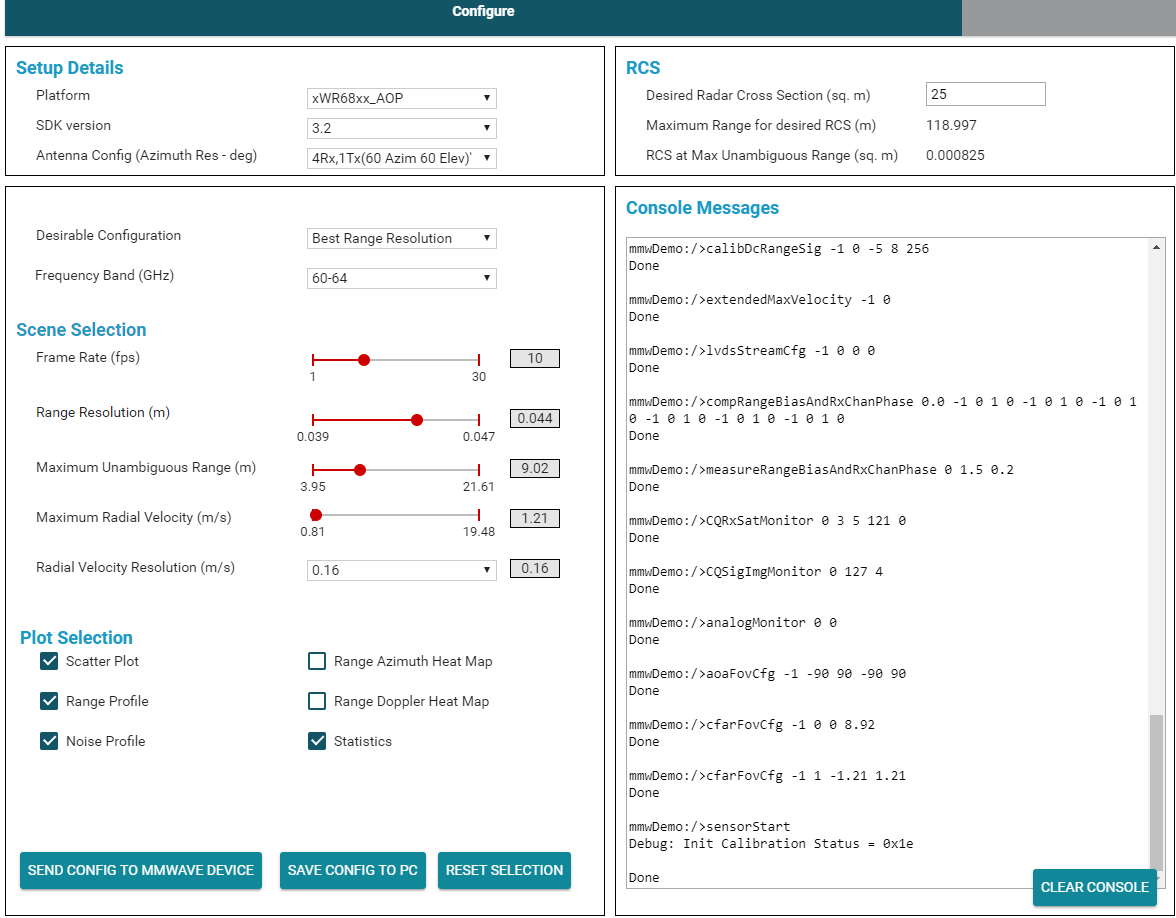
The configuration is below the screen.

Sincelery

  • Hi,

    Thanks for the detailed explanation, however its unclear what you need help with and what you mean by bounce.

    If you are looking for a general explanation of the SDK the SDK users guide discusses that.

    BR,

    Charles O

  • Hello Charles;

    In the above photos, the distance is sometimes 9.1e-41. When measuring the distance of objects, it can sometimes claim that an object exists at a distance that does not exist. So actually the problem is not in the SDK GUI. I think there are two things that cause it.  

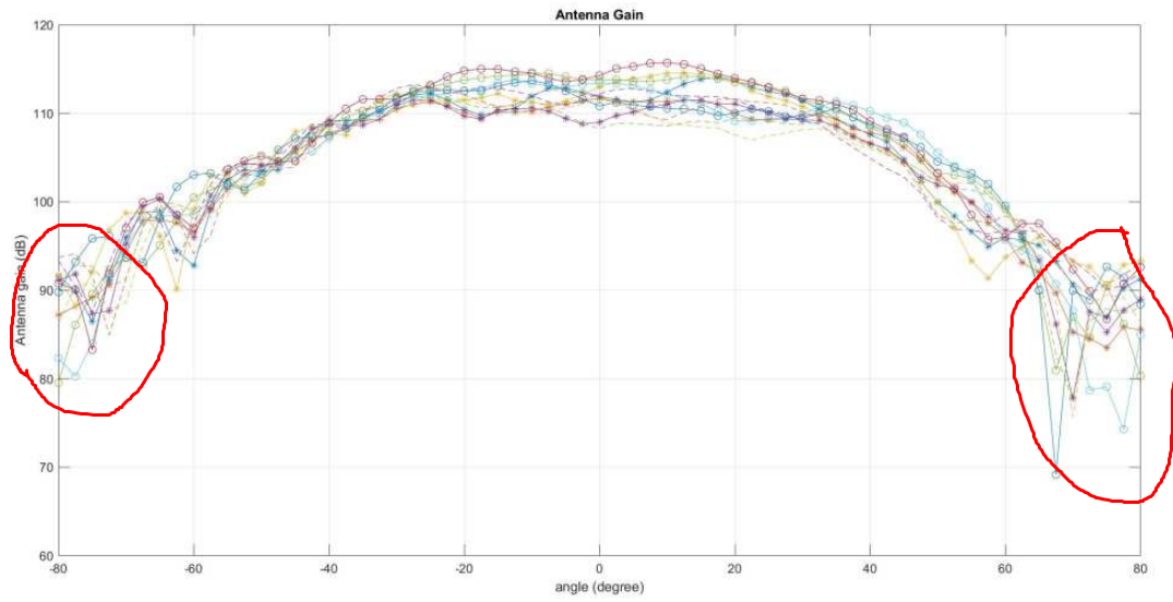
    When I examine the antenna pattern, it may be caused by the noise in the side bands. To prevent this, the reflected signal can be evaluated when it is above 90dB. Related picture as below.

    Another issue;

    In fact, the distance between the transmitted and reflected signal is half of the time elapsed between. (w1-w2) = (delta f / delta t) * t1 = Fmeasurement. If we find t1 here, t1/2 = Range. (delta f / delta t) value is constant.

    1. Where is the chirp modulation signal generated andreflected signal detail within the code?

    2. Its result the exists while there is object. How can I solve this? 80db and over signals should I take the castle?

    Sincelery

  • Hello, 

         Some time due to multi path reflection of the mmWave signals you could expect higher distance of the object than it appears to be.

        In general, mmWave front end configuration is done by firmware (aka BSS firmware), and for this APIs are issued from the mmWave application in the the application processor as shown below


    Typical mmWave radar processing chain using mmWave SDK components shown below. 

    The chirp modulation signal generated and reflected signals are handled by the firmware inside the Radar sub-system.

    All the lower level signaling are abstracted out with higher level API commands... 

    For generation of chirping signals high level commands are provided by the mmWave APIs ( Profile Configuration, Chirp configuration and Frame configuration).  From the MSS applicaiton these values are taken through mmWave APIs, passed through mmWavelink, There are low level drivers which takes this information and passes it to mmWave front end through the BSS fimware, which controls the RF front end. 

    There are various stages of handshakes happens during this process, these are agnostic to end user as shown below.

    If you want to review the chirp configuration you may want to review the configuration in Profile config, Chirp config and frame config. section in the command file. 

    All these details are provided in the SDK user-guide, you could find more information from the below link:

    C:\ti\mmwave_sdk_03_0x_00_0x\docs\mmwave_sdk_user_guide.pdf. 

    Thanks and regards,

    CHETHAN KUMAR Y.B.