


Hi TI,
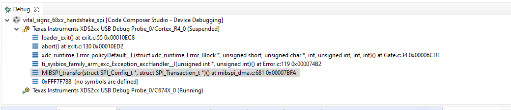
Problem: I was trying to send enable the SPI communication to send messages from the IWR6843 SPI Slave (within MMwaveICBoost board) to an external microcontroller that will serve as SPI Master. Here is a snippet of my code, and the stack dump of the error that happen when I call SPI_transfer( )..
SPI Initial Test (without radar): I had enabled the #define SPI_MULT_ICOUNT_SUPPORT in the mibspi_dma.c and recompile the mmwave SPI Driver as I am planning to send more data thru SPI lines. I had tried sending dummy msg like 0,1,2,3... and it is working well across 256 uint16_t words send in 2 SPI transactions.
SPI Actual Test (with radar): Then, I start running the IWR6843 DSS to get the chirp data output from the regular demo, and then on the way back thru the MmwDemo_mboxReadTask( ), it send the data thru UART as usual first and then I send it thru my SPI channel next. This is the part I am getting the issue at.
Code
void SPI_Init_Fcn() { SPI_Params params; DMA_Params dmaParams; /* Init SYSDMA params */ DMA_Params_init(&dmaParams); /* Open DMA driver instance 0 for SPI */ dmaHandle = DMA_open(0, &dmaParams, &errCode); if (dmaHandle == NULL) { System_printf("Open DMA driver failed with error=%d\n", errCode); return; //jgi } SPI_init(); /* Setup SPI Parameters */ SPI_Params_init(¶ms); params.frameFormat = SPI_POL0_PHA1; //jgi, why did you change the phase? //was SPI_POL0_PHA1 params.pinMode = SPI_PINMODE_4PIN_CS; params.shiftFormat = SPI_MSB_FIRST; params.dataSize = 16; params.transferMode = SPI_MODE_BLOCKING; //jgi, added /* Enable DMA and set DMA channels to be used */ params.dmaEnable = 1; params.dmaHandle = dmaHandle; params.eccEnable = 1; params.mode = SPI_SLAVE; params.u.slaveParams.chipSelect = 0; params.u.slaveParams.dmaCfg.txDmaChanNum = 1U; params.u.slaveParams.dmaCfg.rxDmaChanNum = 0U; //params.transferTimeout=TIMEOUT_MS; //SemaphoreP_pend description says to set timeout in ms, not system ticks as TI docs say //jgi: was enabled spiHandle = SPI_open(0, ¶ms); } void SPI_Send_Transaction() { SPI_Transaction transaction; // send a large transaction tx_ready = LARGE_MSG; transaction.count=sizeof(tx_ready); transaction.txBuf=&tx_ready; transaction.rxBuf=&rx_ready; SPI_transfer(spiHandle, &transaction); //this is where the issue is! }
Let me know some insights or things I could try to make it proceed properly. Thanks so much .

